Newsletter Subscribe
Enter your email address below and subscribe to our newsletter
Enter your email address below and subscribe to our newsletter
All voices matter
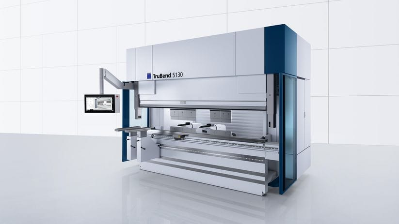
Operating a CNC press brake for the first time can feel overwhelming. The control screen is filled with unfamiliar icons, the machine has multiple moving components, and every bending parameter seems important enough to make or break the final part. Yet, once beginners understand the logic behind CNC press brake operation, the workflow becomes predictable and even intuitive. Modern machines—from brands like Amada, Trumpf, Bystronic, LVD, and Delem-based Chinese manufacturers—are designed around a structured bending path that guides operators step-by-step from setup to production.
In today’s sheet-metal fabrication industry, CNC press brakes have replaced manual and NC machines largely because of their ability to maintain consistency, reduce scrap, and simplify complex bends. For new operators entering a factory or training center, learning CNC press brake operation is not only about memorizing buttons but also understanding how the bending process works as an integrated system. From tooling selection to backgauge positioning, and from safety checks to quality inspection, every step builds on the previous one. Authoritative manufacturing associations such as the Fabricators & Manufacturers Association (FMA) and safety organizations like OSHA emphasize the importance of systematic operator training in ensuring bending accuracy and workplace safety.
This guide breaks down the beginner learning path into digestible, practical sections. Instead of listing technical parameters in a cold instructional tone, the article explains how each action influences the machine, the workpiece, and the final bending result. Readers can expect a complete introduction to machine structure, controller logic, foundational bending concepts, and proven methods used by professional operators around the world. Whether you are a newcomer in a fabrication workshop or an engineer evaluating press brake investment, this guide will give you the confidence to operate a CNC press brake safely and effectively.
A CNC press brake is a computer-controlled machine designed to bend sheet metal by pressing it between a punch and a die. While traditional mechanical and hydraulic brakes rely heavily on manual skill, a CNC press brake simplifies the process by using a controller to automate positioning, bending depth, angle compensation, and even sequencing. The machine reads operator inputs such as material type, thickness, bend angle, tooling, and flange size, then calculates the required ram movement and backgauge position. This integration allows operators to focus on accuracy rather than repetitive mechanical tasks. For deeper technical definitions, standards such as ISO/TC 164 Metal Forming Standards and controller references like Delem CNC Systems provide authoritative explanations of press brake technology and terminology.
At its core, a CNC press brake transforms flat sheet metal into shaped components through a controlled deformation process known as air bending. Most bends in the industry rely on this technique because it offers great flexibility in achieving different angles with a single set of tools. When a machine lowers the punch onto the sheet, the metal undergoes elastic and plastic deformation until the desired angle is achieved. Sensors or algorithms compensate for springback, which varies by material. Understanding these principles helps beginners avoid common errors such as under-bending, over-bending, or inconsistent results. Industry resources such as The Fabricator – Bending Basics provide practical insight into air bending mechanics and springback behavior.
CNC press brakes also come in several configurations depending on the driving system. Hydraulic press brakes remain the most widely used, offering reliability and strength for general fabrication. Electric press brakes provide fast cycling and precision for thin-sheet industries such as electronics and appliances. Hybrid designs combine both technologies to balance speed, energy efficiency, and force. Tooling manufacturers such as WILA further detail how different press brake systems interact with tooling geometry and bending accuracy. Regardless of the mechanical system, the CNC control functions in a similar manner, guiding operators through program creation, tooling setup, and production.
Learning proper CNC press brake operation early creates habits that influence the operator’s entire career. New users who understand the logic behind the controller will be able to troubleshoot issues independently, rather than relying entirely on senior operators. They will also develop a clear mental map of the bending sequence, making it easier to predict how each bend affects the next. Authoritative training resources, such as the Fabricators & Manufacturers Association (FMA), emphasize that early-stage operator education dramatically improves long-term performance and reduces production errors.
An operator who understands the machine’s structure—such as how the Y1/Y2 axes move independently or why the crowning system adjusts the table—can make informed decisions when the final part does not match expectations. Recognizing the relationship between tooling height, backgauge fingers, and material support prevents errors that could otherwise damage tools or cause scrap. Tooling manufacturers like WILA provide detailed technical explanations on how tool alignment and crowning affect bending accuracy.
Another important reason is safety. Press brakes generate enormous force, and incorrect handling can cause severe injury. Beginners must build a habit of checking tool alignment, backgauge clearance, ram movement, and hand positioning before every bend. A structured operating method not only protects workers but also improves production stability. Most workplace accidents are caused not by machine failure but by operators rushing through setup or skipping essential steps. Regulatory bodies such as OSHA consistently highlight the critical role of standardized procedures in preventing press brake injuries.
Finally, proper CNC press brake operation is essential for maintaining equipment lifespan. Modern brakes are precise machines, and mishandling the ram, overloading tools, or using incorrect crowning settings can create long-term wear that affects accuracy. Learning to operate the machine responsively—adjusting pressure, speed, and position as needed—keeps the machine performing optimally for many years.
Before diving into actual operating steps, this article follows a structured path that mirrors the training method used in professional factories:
Each section builds upon the previous, ensuring beginners gain both theoretical knowledge and real-world techniques used in daily production.
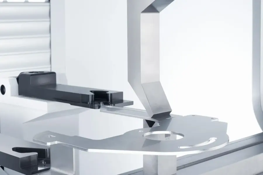
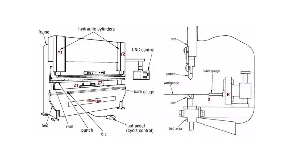
Before an operator can confidently run a CNC press brake, they must understand the machine’s key components and the terminology used by technicians and engineers in daily production. Each mechanical part interacts with the others, and knowing their function helps beginners grasp why certain bending results occur and how to adjust the machine when something goes wrong. This section breaks down the machine in a practical way, focusing not on memorizing names but on building a mental picture of how the entire system behaves during operation.
The ram is the upper moving beam of the press brake, responsible for pushing the punch down toward the die. On modern CNC machines, the ram is controlled by two independent servo-hydraulic cylinders or electric actuators labeled Y1 and Y2. Although the two sides of the ram appear to move together, they are constantly monitored and adjusted to maintain parallelism. This independent movement allows the machine to correct slight differences caused by material thickness variations or thermal expansion. Manufacturers such as TRUMPF and control system providers like Delem publish detailed explanations on how modern CNC systems control Y1/Y2 axis synchronization and ram accuracy.
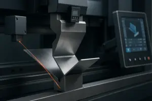
When a bend takes place, the ram moves through three important positions: approach, bending, and decompression. Understanding these stages helps operators tune the speed settings and determine how much dwell time is needed for a stable angle. Beginners often struggle with inconsistent angles not because of material issues but because they do not realize how the ram transitions between these positions. With proper training, they learn to observe the ram movement closely and recognize when its path deviates from normal behavior. Technical articles on bending dynamics—such as those offered by The Fabricator—provide further insight into ram motion control and its effect on angle stability.
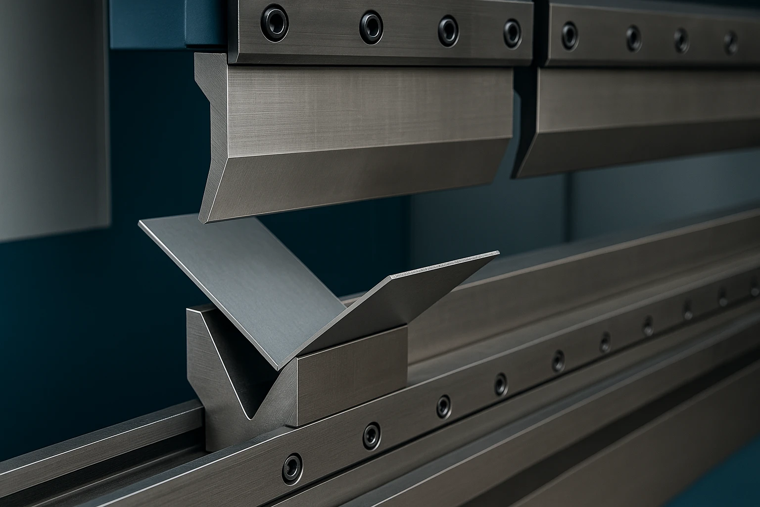
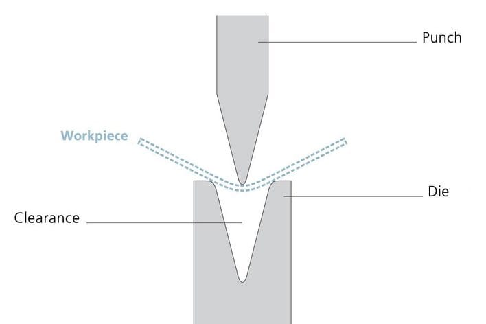
Tooling selection is one of the most influential factors in achieving accurate bends. The punch forms the upper tool, shaping the metal by pressing it into the die, which acts as the lower support. While tooling may appear simple, its geometry determines the force required, the achievable angle, and the precision of the bend. Most fabrication shops rely on standard air bending tools because a single V-die can produce multiple angles by controlling penetration depth.
Choosing the correct die opening is more than following a chart; it is about understanding the relationship between material behavior, machine tonnage, and minimum flange lengths. A beginner who learns these fundamentals develops an instinct for matching the right tool to the workpiece. Using the wrong die can cause excessive tonnage, poor angle accuracy, or even tool breakage. This is why professional operators treat tooling as a foundation rather than an accessory.
Over time, beginners also learn to recognize wear patterns on tools. Small imperfections on the die shoulders or punch tip can lead to surface scratches or inconsistent angles. Developing the habit of inspecting tools before each setup helps ensure stable production and reduces scrap.
The backgauge acts as the operator’s “third hand” by positioning the sheet metal at the correct distance for each bend. While the Y-axis determines the bending depth, the backgauge defines the flange length. Modern press brakes include several backgauge axes:
Although these axes may appear complicated at first, they work together to support various part sizes and bending sequences. For example, Z-axis movement allows operators to gauge wide panels or parts with asymmetric profiles. R-axis movement is essential when using tall tools or when bending near the top of a large flange. Instead of remembering each axis separately, beginners benefit from understanding the underlying purpose: a flexible positioning system that eliminates manual measuring and reduces handling errors.
In daily production, the backgauge is often the first component beginners must adjust manually. Developing confidence in its movement and position feedback helps new operators predict how the part will behave during multi-step bending sequences.
The worktable forms the base of the press brake, supporting the die and ensuring the machine maintains straightness during operation. Because the ram experiences high force in the middle during bending, the machine can suffer from natural deflection, resulting in uneven angles from left to right. To counter this, modern press brakes include a crowning system, either mechanical or hydraulic, which slightly adjusts the table curvature to maintain parallelism. Leading tooling and compensation system manufacturers such as WILA and major machine builders like LVD provide detailed explanations of crowning technology and how it corrects table deflection during bending.
Understanding crowning is important because beginners often face the problem of angle differences between the center and edges of the workpiece. Instead of assuming the material is inconsistent, they must consider whether the crowning value is appropriate. With experience, operators learn to recognize the subtle visual cues that indicate crowning misalignment, such as a gradual angle shift across the length of a long part. Technical resources from The Fabricator further explain how deflection and crowning affect angle consistency across long bends.
The crowning system represents a crucial link between the theoretical bending program and actual results. Without it, even the most carefully prepared program can fail to deliver consistent angles.
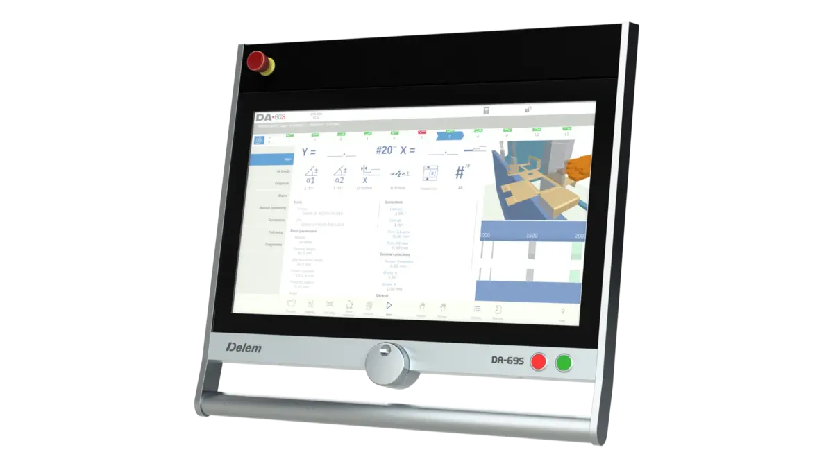
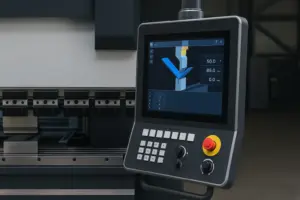
The controller serves as the “brain” of the press brake. It reads operator inputs, calculates bending parameters, moves each axis, and monitors the entire process. Different brands feature different user interfaces, but the logic behind them is similar. Most controllers guide the operator through:
Beginners often worry about memorizing every button or menu, yet effective operation relies more on understanding the controller’s purpose than its layout. A well-trained operator uses the controller not as a static display but as a decision-making tool. Instead of mechanically entering values, they check whether the machine’s recommended parameters make sense for the part. This habit prevents accidental overbending or tool collision, especially during complex sequences.
As beginners gain experience, they learn to interpret the controller’s feedback messages. When the machine displays warnings about axis interference or insufficient tonnage, operators who understand the logic behind these warnings can respond quickly and correctly.
CNC press brakes incorporate several safety systems to protect operators from accidents. The most common is the light curtain, which creates an invisible barrier in front of the machine. If any object passes through this barrier while the ram is descending, the machine halts immediately. Understanding how this system interacts with the ram’s movement is essential because beginners sometimes confuse safety stops with machine malfunction.
Other safety features include laser protection, two-hand control modes, emergency stop buttons, and guards around the back of the machine. Learning to operate within these constraints builds a habit of caution that stays with operators throughout their career. Unlike tooling or controller parameters, safety rules are non-negotiable; understanding them is as important as mastering bending techniques.
Before beginners start bending their first sheet metal part, they must understand the fundamental principles that determine how metal behaves under pressure. CNC press brakes are precise machines, but accuracy ultimately depends on how the operator interprets material characteristics, springback effects, bending methods, and tooling geometry. These factors influence each other in ways that are not always obvious at first glance. By learning these basics early, operators build the technical intuition needed to troubleshoot bending issues and make informed adjustments during production.
When a press brake bends a sheet, the metal undergoes a combination of elastic and plastic deformation. In the early stage of the bend, the material stretches but can still return to its original shape. As the punch continues pressing downward, the deformation passes a threshold where the metal permanently changes shape. The inner region of the sheet experiences compression, while the outer region stretches. Understanding this internal distribution of forces helps beginners appreciate why the metal sometimes springs back after the ram retracts. Foundational metal deformation principles are well-documented by materials organizations such as ASM International and engineering reference sources like MatWeb, which provide detailed explanations on elastic vs. plastic behavior.
The boundary between elastic and plastic zones varies with different materials. Mild steel transitions earlier and is relatively predictable, while stainless steel maintains elasticity longer, causing greater springback. Aluminum behaves differently due to its lower yield strength, making it prone to cracking if the bending radius is too tight. By observing how each material reacts, operators learn to anticipate these outcomes before they occur. Industry-focused publications such as The Fabricator often highlight these material-specific bending characteristics and how they influence springback.
New operators often assume that the press brake forces the metal into a strict angle regardless of its internal characteristics. In reality, the machine guides the bend, and the metal’s behavior determines the final result. This understanding allows beginners to treat bending as a controlled negotiation between machine force and material resistance, rather than expecting absolute conformity.
Springback is one of the most important concepts in press brake operation. After the punch leaves the material, the elastic portion of the bend attempts to return to its natural state, causing the angle to open slightly. The extent of springback depends on material type, hardness, thickness, grain direction, and die opening. Stainless steel typically exhibits more springback than mild steel, and high-strength steel shows significantly more rebound.
A beginner must learn that springback is not a mistake or a sign of incorrect programming; it is an inherent property of metal. The goal is to compensate for it. CNC press brakes account for springback through deeper punch penetration, automatic angle correction, or crowning adjustment. Most controllers allow the operator to enter material data so the system can estimate required corrections, but this estimation is not perfect. Operators should always confirm the first part with a protractor or angle measurement tool.
With experience, operators develop a sense of how each material behaves. They learn that a 90° bend programmed in the controller may require a penetration depth closer to 88° to achieve the desired final result. This understanding helps them correct angles efficiently without wasting material.
CNC press brakes use three main bending methods, each offering different levels of accuracy and tonnage requirements. Beginners often hear these terms without fully grasping the differences, which can lead to incorrect expectations.
Air bending is the most widely used method today. The punch does not force the sheet to touch the bottom of the die; instead, the angle is controlled by the depth of the punch. A single V-die can produce many angles, making this method flexible and economical. However, air bending is more sensitive to springback, requiring careful compensation.
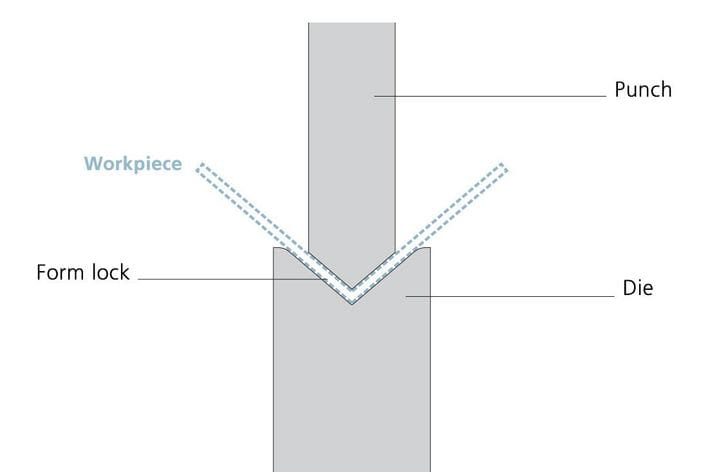
Bottom bending brings the sheet into firm contact with the die shoulders, reducing springback because the metal conforms more closely to the die geometry. This method requires higher tonnage and precise tool matching but offers greater angle stability, especially for stainless steel.
Coining, the oldest method, presses the sheet deeply into the die, altering the metal’s molecular structure. Coining nearly eliminates springback but requires significantly higher tonnage, often exceeding what modern machines are designed for. As a result, coining is rarely used except for specialty applications.
Understanding these distinctions helps beginners appreciate why most factories prefer air bending for general production. It offers the best balance of flexibility, efficiency, and tooling cost. Operators who master air bending gain the foundation needed for nearly all bending tasks they will encounter.
One of the most critical decisions an operator makes is choosing the correct V-die opening. A common rule of thumb is that the die opening should be six to eight times the material thickness. For example, a 1 mm sheet typically pairs with a 6–8 mm die. While this guideline works in most cases, real-world bending requires more nuance.
A larger die opening reduces tonnage and eases the bending process but increases springback and bending radius. A smaller die opening enhances angle accuracy but risks cracking the material or damaging the tooling if excessive force is applied. Beginners must note that certain materials, such as aluminum or cold-rolled steel, are more sensitive to tight die openings. Choosing the wrong opening leads to inconsistent results, even if the bend angle appears correct at first glance.
With time, operators learn to inspect the sheet’s behavior during trial bending. If the material shows signs of stretching unevenly or the angle varies from left to right, the die opening may need adjustment. Developing this attention to detail helps operators transition from following basic rules to making decisions based on real bending conditions.
Sheet metal is produced by rolling, which creates a grain direction. Bending parallel to the grain increases the risk of cracking because the internal structure aligns with the bend line. Bending perpendicular to the grain generally produces cleaner bends with less resistance.
Beginners often overlook grain direction, assuming all sheets behave identically. In practice, grain direction affects springback, bend radius, and required force. When operators learn to identify grain direction on a sheet, they become better at predicting potential issues. If the part design forces a bend parallel to the grain, the operator can compensate by choosing a larger die opening or adjusting the punch radius.
Part designers sometimes ignore grain direction when creating drawings, leaving the operator responsible for making practical adjustments on the shop floor. Understanding this relationship helps beginners communicate more effectively with engineers and avoid unnecessary scrap.
Although beginners do not need to perform complex bending calculations, they should understand why flat-pattern dimensions differ from finished part dimensions. When metal bends, the inner surface compresses while the outer surface stretches, creating a neutral axis in between. The location of this neutral axis determines the bend allowance — a value used for calculating the correct blank size. Industry engineering references such as Engineers Edge and fabrication guides like The Fabricator – Bend Allowance Basics provide detailed explanations of bend allowance formulas used across sheet-metal design.
The K-factor expresses how far the neutral axis shifts during bending. A higher K-factor indicates more stretching, which increases the bend allowance. While CNC press brakes often calculate these values automatically, operators benefit from understanding the concept. This awareness helps them recognize when a flat-pattern discrepancy comes from inaccurate bend allowance rather than machine error. International design standards referenced by organizations like ASME also emphasize the importance of K-factor selection in accurate sheet-metal development.
A CNC press brake is only as effective as the program behind it. While the machine provides the physical force needed to bend metal, the controller determines how each movement is executed. For beginners, learning the controller interface can feel intimidating because the display is filled with menus, icons, and technical parameters. However, once operators understand the logic behind these screens, they realize that every controller follows a similar structure—no matter whether the machine is equipped with Delem, Cybelec, ESA, Amada, or Bystronic controls.
This section explains how a controller thinks, how bending programs are created, and how operators can master the core functions without memorizing unnecessary details. By building a conceptual understanding, beginners can quickly adapt to any press brake in the factory.
Although interface layouts differ among brands, CNC controllers share the same operational philosophy: they translate the operator’s intentions into precise axis movements. Instead of moving the ram manually or aligning the sheet by eye, operators input instructions that tell the machine how deep to bend, where to position the backgauge, and how the bending sequence should progress.
Controllers achieve this by connecting material data, tooling information, and geometric requirements into a program. Each parameter is linked to others, forming a structured path that ensures the machine understands both the individual bend and the overall part. Beginners sometimes assume the controller produces the finished part automatically once they enter a bend angle. However, the controller is more like a sophisticated assistant—it provides guidance, but the operator must supply correct information.
Understanding this relationship helps new users avoid a common mistake: relying solely on the controller’s recommendations without evaluating whether they make sense. The most successful operators use the controller to confirm their reasoning rather than to replace it.
The first step in most bending programs is entering basic material information, such as type, thickness, and sometimes tensile strength. Many beginners underestimate how important this step is because they assume all sheets of the same thickness behave similarly. In practice, the controller uses this data to estimate springback, tonnage requirements, and bending depth.
When operators enter incorrect material data—for example, labeling stainless steel as mild steel—the controller may underestimate the force required and produce inaccurate bends. This mismatch often leads beginners to think the machine is malfunctioning. Understanding how material input influences calculations helps them appreciate why the first trial bend sometimes needs manual adjustment.
In advanced controllers, material databases allow factories to store customized values based on actual sheet behavior. Beginners eventually learn how to update these values to reflect real-world conditions, improving consistency over time.
Choosing the correct punch and die inside the controller is essential for achieving accurate bends. The tooling library contains detailed geometric profiles of each tool, including height, angle, radius, and die opening. When operators select a tool from this library, the controller automatically adjusts the ram reference point and calculates the appropriate penetration depth. Leading tooling manufacturers such as WILA and Wilson Tool publish detailed data regarding punch and die geometry, helping operators understand how digital tooling libraries reflect real-world tooling dimensions.
Beginners may be tempted to skip this step or choose the closest-looking tool rather than the exact model being used. Even a small mismatch between actual and virtual tools can result in angle deviations or collisions. By learning to match tools carefully, beginners avoid mistakes that experienced operators often warn about. Technical bending guidelines from organizations such as Mate Precision Tooling further emphasize the importance of correct punch–die pairing.
As operators become familiar with the tooling library, they begin to see patterns between tool geometry and bending results. They understand why certain punches work better for acute angles, or why a wider V-die provides more tolerance for thicker materials. This intuition speeds up program creation and reduces the number of initial adjustments needed during trial bending.
A bending program consists of multiple steps, each corresponding to a bend in the part. Controllers allow operators to enter bend angles, flange lengths, backgauge positions, and ram movements for each step. The sequencing of these bends is crucial because the order determines how the part is handled and whether the operator can physically complete each bend without interference.
Beginners often assume the controller automatically knows the best sequence. While some advanced systems include automatic sequencing, the operator must still evaluate feasibility. For instance, bending a small flange before a larger one may make it impossible to insert the part into the die for the next step. Learning to think ahead—imagining how the part will rotate and interact with the backgauge—helps beginners design programs that minimize handling difficulty.
Controllers typically visualize the part in a 2D or 3D simulation, allowing operators to confirm whether the sequence works. This simulation is not just an animation—it is a practical tool that helps beginners understand how the part will move. When operators align the program with the actual workshop workflow, they achieve a smoother production experience.
Backgauge settings are essential for defining flange lengths. When creating a program, operators input the required dimensions, and the controller calculates the backgauge position. However, these calculations depend on accurate tool and material data. If the die opening or punch radius is incorrect, the backgauge may position the sheet slightly off, causing dimension errors.
Beginners should learn to observe how the backgauge behaves during test bends. If the metal drifts or buckles, or if the backgauge fingers do not support the sheet evenly, the operator may need to fine-tune R-axis or Z-axis positions. Small adjustments during setup often lead to significant improvements in part accuracy.
Understanding backgauge movement also helps beginners avoid collisions. When switching between large and small flanges or working with complex parts, the backgauge may retract or rotate automatically. Operators must remain aware of these movements to prevent the sheet from striking the fingers or getting trapped.
At the heart of each bend lies the ram’s penetration depth, which determines the final angle. Controllers allow the operator to define how far the ram descends, how long it dwells at the bottom, and how quickly it retracts. Dwell time is especially important for materials with high elasticity, such as stainless steel, because holding the ram for an additional moment allows the material’s internal forces to stabilize.
Beginners often assess angle accuracy based on a single test bend, but materials behave differently across various widths. Learning to adjust ram depth by small increments helps operators achieve consistent results across long parts. Controllers typically include angle correction functions that allow operators to enter measured angles, enabling the system to refine its calculations automatically.
This feature does not replace operator skill; instead, it supports it. By combining careful observation with controller-assisted correction, beginners achieve accurate results with fewer adjustments.
Once a program is complete and the first part meets quality standards, operators must save the program correctly. Modern controllers allow programs to be organized by part number, customer name, or production batch. Beginners often overlook this administrative step, but proper documentation prevents confusion during future production runs.
Experienced operators also recommend saving version notes when programs are adjusted. This habit creates a record of what worked and why certain parameters were changed, helping future operators reproduce results without trial-and-error.
Learning to operate a CNC press brake becomes much easier once beginners understand the workflow that every experienced operator follows. Although machines differ in features, all CNC press brakes share a common sequence that guides the operator from powering the machine on to producing the first acceptable part. This workflow not only ensures accuracy but also creates a habit of safe operation—a crucial skill in environments where heavy machinery and high force are involved. Industry organizations such as the Fabricators & Manufacturers Association (FMA) and safety regulators like OSHA consistently emphasize standardized workflow adherence as the foundation of safe and consistent bending.
The following workflow does not present isolated actions; instead, each step builds on the previous one. The goal is to help beginners understand the reasoning behind each action so they can apply these principles to any press brake, regardless of brand or controller model. Major machine manufacturers such as TRUMPF Training Services provide structured operator training programs that mirror this progressive learning path and reinforce the importance of step-by-step methodology.
The operating process begins before any metal is placed on the table. When powering the machine on, the operator must ensure the emergency stop buttons are reset, the hydraulic system is ready, and all axis references are established. As the machine initializes, the controller activates internal calibration routines for the Y1 and Y2 axes to ensure the ram is level. Some machines perform this automatically, while others require the operator to start the calibration manually.
Beginners often underestimate the importance of this initial calibration. Even a small deviation in ram parallelism can produce angle inconsistencies across the part. Watching the ram move slowly during calibration also helps beginners visualize how the machine balances force on both sides of the beam. Once the calibration completes, the ram returns to its home position, indicating that the machine is ready for programming.
At this stage, operators should listen for abnormal sounds from the hydraulic pump or notice any latency in ram movement. A slow or uneven movement may signal issues with the hydraulic system, oil temperature, or sensors. Identifying these problems early prevents defective parts and minimizes downtime.
Before touching the controller, operators must study the part drawing. This includes understanding the bend angle, flange lengths, bend sequence, and tolerances. The drawing also indicates important details such as inside radius, grain direction, and any critical dimensions that should not be altered.
Beginners sometimes rush into program creation without fully understanding the drawing, leading to difficulties later in the workflow. A proper review of the drawing allows the operator to plan how the sheet must be rotated during each bend and whether the backgauge will support the part adequately. If the drawing includes tight tolerances, the operator must pay special attention to tooling selection and crowning values.
Thinking about the part holistically ensures that the operator treats the bending process as a controlled transformation rather than a series of disconnected actions.
Tool selection is one of the most influential factors in the success of the first bend. Operators must choose a punch and die appropriate for material thickness, desired angle, and minimum flange length. After selecting the tools, they should inspect the punch tip and die shoulders for wear, damage, or debris. Even minor imperfections can imprint marks on the sheet or cause inconsistent angles.
Installing tools into the machine must be done carefully. Clamping systems—whether manual, hydraulic, or quick-clamp—must secure the punch firmly so that it stays aligned during bending. Misalignment causes angle variation and can even create dangerous collisions. Beginners should learn to visually confirm that the punch is fully seated in the clamp and that the die is centered on the worktable.
A final check ensures that the tool height matches what is selected in the controller. This alignment between physical tools and programmed tools prevents ram position errors and ensures accurate penetration depth.
Once the tools are installed, the operator loads the program created earlier or begins entering the bending steps manually. This includes confirming material type, thickness, bend angles, flange lengths, and bend sequence. Checking these parameters carefully avoids errors that would otherwise surface during the first trial bend.
Beginners should take time to review the controller’s recommendations for die opening, tonnage, and penetration depth. Understanding these values reinforces earlier theoretical knowledge and helps them connect the controller’s calculations with real-world bending behavior. Before proceeding, operators must review the safety screens and axis interference checks displayed by the controller. These checks ensure that the backgauge and tools have sufficient clearance.
The simulation feature, if available, should be used to visualize how the part moves during each bend. This step prevents handling problems and allows operators to anticipate potential collisions or awkward rotations.
Once the program is ready, operators bring the backgauge into the initial position. The way the sheet rests against the backgauge determines whether the flange is accurate, so beginners must learn to observe the contact point carefully. If the sheet does not sit evenly, the operator may need to adjust the Z-axis for finger spacing or the R-axis for finger height.
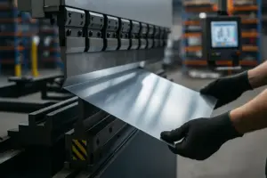
Longer sheets often require additional support. Beginners must recognize when the part is too heavy for the backgauge alone and use support arms or assistant devices to avoid deflection. Failure to support the part properly can lead to dimension errors, bending misalignment, or even injury. Understanding how the backgauge works as part of a larger support system helps operators handle wide or irregularly shaped parts confidently.
The first trial bend is the moment when theory meets reality. With the sheet positioned against the backgauge, operators engage the foot pedal, prompting the ram to descend. Beginners should observe the ram movement closely, noting the transition from rapid approach to controlled bending speed. High-precision measurement tool providers such as Mitutoyo offer detailed guidance on how controlled motion influences angle accuracy and measurement reliability.
After the ram retracts, the sheet should be removed carefully and placed on a flat surface for angle measurement. The operator uses an angle protractor or digital gauge to determine whether the result matches the drawing. If the angle is slightly open or closed, small adjustments to penetration depth compensate for springback. This is a stage where beginners begin to understand the practical impact of material behavior. For angle verification, equipment manufacturers such as Keyence provide examples of digital measurement devices commonly used in metal fabrication.
Observing how the sheet behaves during this first bend teaches operators more than any theoretical explanation. It demonstrates how stiffness, grain direction, and tool radius influence the final angle. This real-world feedback becomes the foundation for developing bending intuition. Articles on bending mechanics from The Fabricator further explain how grain direction and elastic recovery affect trial bend results.
After verifying the angle, operators must measure the flange length to confirm the backgauge position is correct. If the flange dimension deviates from the drawing, small adjustments to the X-axis may be necessary. Beginners often discover that even minor misalignment in how the sheet touches the backgauge can produce noticeable errors. With experience, they learn to reposition the sheet more consistently, which improves accuracy during production.
Crowning adjustments may also be required if angles vary from left to right. Beginners should be taught not to rely solely on controller recommendations but to interpret the part’s behavior and adjust crowning accordingly. Understanding crowning transforms the operator from a passive follower of the program into an active controller of bending accuracy.
Once the trial bend meets specifications, the operator begins full production. During repetitive bending, beginners must watch for gradual shifts in angle or flange length caused by material inconsistencies, tool wear, or temperature changes in the hydraulic system. Experienced operators do not assume a stable process remains stable indefinitely; they inspect parts at regular intervals to catch small deviations before they accumulate.
Beginners must also remain aware of the machine’s rhythm—changes in sound, ram speed, or backgauge behavior may indicate issues developing in the background. Learning to sense these subtle signals helps operators respond quickly and keeps production running smoothly.
After production ends, operators must clean the work area, remove metal scraps, and wipe the tools to prevent corrosion. Storing tools properly ensures their geometry stays intact. Finally, the machine must be shut down following the manufacturer’s recommended procedure, allowing the hydraulic system to depressurize gradually.
Developing good end-of-shift habits maintains machine accuracy and extends equipment lifespan. Beginners who learn these routines early become reliable operators who take pride in caring for their machines.
Producing a good bend on a CNC press brake is only half of an operator’s responsibility; the other half is verifying that the part meets dimensional and geometric requirements. Even when a program seems correct, small variations in material properties, tooling wear, or backgauge contact can create deviations that only careful inspection can detect. Quality inspection is not a separate activity—it is part of the bending process itself, guiding operators toward consistent and reliable production. Precision measurement manufacturers such as Mitutoyo and industrial metrology experts like ZEISS Metrology provide comprehensive references on dimensional accuracy and inspection methodology in metal fabrication.
New operators often focus solely on the angle of the bend. While angle accuracy is crucial, a complete inspection also evaluates flange dimensions, straightness, flatness, radius consistency, and the presence of surface defects. Each of these indicators reveals important information about how the bending process behaved. Learning to interpret these signs allows beginners to correct issues at their source rather than compensating blindly. Industry guides such as The Fabricator offer practical examples of common defect patterns and how they relate to material, tooling, or backgauge stability.
Angle measurement begins immediately after the first trial bend. Operators typically place the part on a stable surface and check the angle using a protractor or a digital angle gauge. Beginners are encouraged to take measurements at multiple locations along the bend—left, center, and right—because a single measurement cannot reveal whether the angle is consistent. Any variation across the length often hints at improper crowning or uneven material behavior.
Angle inspection reveals more than whether the programmed value is correct. It also helps beginners observe how the material responded to pressure and springback. For example, an angle that consistently returns to a slightly open position suggests that the ram penetration depth is insufficient. In contrast, an angle that is too tight may indicate overcompensation or an incorrectly matched punch radius.
With experience, operators learn to evaluate angles not just numerically but visually. A subtle curvature along the bend line or an unexpected twist may suggest that the sheet was not fully seated against the backgauge or that the material itself has internal stresses. This visual intuition, combined with precise measurement, forms the basis of accurate inspection.
While angles define the shape, flange lengths define the part’s function. Even when the angle is correct, a flange that is too short or too long makes the part unusable. Beginners quickly learn that flange dimensions are sensitive to errors in backgauge positioning, material drift, or inconsistent hand placement during loading.
To verify flange lengths, operators measure from the edge of the sheet to the bend line using calipers or a tape measure. As with angle measurement, checking multiple points along the flange helps identify whether the sheet contacted the backgauge properly. If one side consistently measures short while the other side remains accurate, the operator may need to adjust the Z-axis position of the backgauge fingers.
Dimensional accuracy also reveals information about the controller’s calculations. If consistent deviation occurs across multiple bends, the operator may need to update the material database or adjust the bending factors. Understanding how these deviations connect to material behavior allows beginners to refine programs and reduce future corrections.
Even when angle and dimensions are correct, the bend may not be straight. Straightness issues can arise from uneven pressure distribution, damaged tools, or incorrect crowning values. Operators identify this problem by sighting along the bend line or using a straightedge.
A bend that is tighter in the center than at the ends suggests that crowning is insufficient. A bend that is reverse-curved, with the ends tighter than the middle, may indicate excessive crowning. Tool wear often reveals itself through irregular bend surfaces or slight waviness along the bend line. Recognizing these patterns allows operators to correct the process early and maintain consistent quality.
Flatness problems can also appear when bending thick or long materials. If the sheet bows or rises after bending, the operator should evaluate whether the part was supported correctly. Heavy materials may sag during loading, changing the angle and producing a bowed shape. This situation teaches beginners the importance of part support systems and coordinated handling.
Surface defects provide valuable clues about what happened during bending. Scratches on the sheet suggest that the punch or die needs cleaning or that the surface finish of the tools is worn. Small indentations along the bend line reveal whether the die radius is too sharp or whether the material is softer than expected. For sensitive materials, such as stainless steel, surface protection films may be necessary to avoid cosmetic damage.
Beginners must learn that surface defects, even if they do not affect structural properties, can cause customers to reject parts. This understanding encourages operators to pay attention not only to dimensions but also to appearance. Recognizing patterns in surface defects helps them maintain tools correctly and choose appropriate bending pressures.
Every operator, regardless of skill level, encounters bending errors at some point. What distinguishes professionals from beginners is their ability to trace these errors back to their root causes. Understanding why errors occur enables operators to solve problems logically rather than guessing.
One common error is overbending or underbending. This usually stems from incorrect penetration depth, inaccurate material data, or unaccounted springback. By adjusting the ram depth incrementally and checking the first few pieces carefully, operators develop a reliable correction process.
Another frequent issue is left-right angle variation, often caused by incorrect crowning or variable material thickness. Beginners quickly learn that even high-quality sheets vary slightly, and crowning helps compensate for these differences. When angle differences remain despite crowning adjustments, operators may inspect the tools or check for misalignment in the worktable.
A third issue involves flange length inconsistency, which typically indicates problems with backgauge contact. If the sheet does not rest squarely on both backgauge fingers, it may shift during bending. Operators learn to adjust Z-axis positions or modify part orientation to prevent this drift.
Finally, twisting or bowing of the part often results from uneven support during bending. Long parts require extra attention because gravity affects how the sheet enters the die. Other factors, such as grain direction and material strength, also contribute to twisting. Recognizing these influences helps operators anticipate problems and prepare appropriate support strategies.
Troubleshooting is not about memorizing correction values; it is about understanding how the machine, material, and tooling interact. Beginners should approach each bending problem as a diagnostic puzzle, gathering clues from the part and tracing them back to likely causes. A systematic mindset prevents unnecessary adjustments and helps operators maintain consistency. Industry resources such as The Fabricator – Press Brake Problem Diagnosis emphasize structured troubleshooting as the most effective way to maintain bending quality.
Experienced operators build routines that guide them through troubleshooting. They measure angles from multiple points, verify backgauge alignment, recheck crowning values, and observe tool conditions. They never assume errors come from a single cause; instead, they analyze the situation as a combination of factors. Discussions in professional machining communities like Practical Machinist frequently highlight how multi-factor analysis leads to more accurate problem identification in real-world fabrication environments.
Beginners who adopt this mindset early become more confident and capable. Instead of feeling overwhelmed by errors, they treat each challenge as an opportunity to deepen their understanding of the bending process. Manufacturing education organizations such as SME (Society of Manufacturing Engineers) encourage this mindset as a core competency for developing long-term expertise in metal forming.
Even with a correct program, appropriate tooling, and a well-calibrated machine, beginners will inevitably encounter bending issues during production. Troubleshooting is not a sign of failure—it is a normal part of CNC press brake operation. What separates skilled operators from inexperienced ones is the ability to diagnose problems based on evidence rather than assumptions. This section guides beginners through a logical approach to troubleshooting, helping them develop the confidence needed to resolve issues consistently and efficiently.
Troubleshooting should be approached as a structured conversation between the operator and the part itself. Every deviation in angle, dimension, or straightness reveals what happened during the bending process. By reading these signs correctly, operators can trace the issue back to its source and apply the correct remedy without unnecessary trial-and-error.
A common difficulty beginners face is achieving the correct bend angle despite entering the right values into the controller. While it might seem that the machine should simply follow the program, bending accuracy depends on far more than digital instructions.
If the angle is consistently too open, the most likely cause is springback. Certain materials, such as stainless steel, require deeper penetration to compensate. Beginners should adjust the ram depth in small increments—typically 0.05 to 0.10 mm—until the angle matches the drawing.
If the angle is too tight, the operator may have overcompensated during a previous adjustment. In this case, reducing penetration depth gradually helps bring the angle back into tolerance. Another potential cause is incorrect tool selection. A punch with a sharper radius or a die with a smaller opening naturally creates tighter angles. Understanding these relationships helps operators adjust intelligently.
Occasionally, incorrect angles arise because the punch and die height do not match the tooling selected in the controller. Even a few millimeters of mismatch can affect penetration calculations. Beginners should check that the physical tools correspond exactly to those chosen in the controller.
Left-right angle inconsistency is one of the most frustrating issues for beginners. The part may measure correctly in the center but show variations at the edges, or vice versa. This problem rarely originates from a single cause; instead, it reflects how the machine, tools, and material interact.
The most common factor is crowning. If the crowning value is too low, the center of the bend becomes tighter than the ends. If it is too high, the center opens while the edges remain tight. Adjusting crowning based on the observed pattern allows the operator to restore consistency.
Uneven material thickness also contributes to angle variation. When sheets vary in thickness across their width, the metal responds differently to pressure. This is especially common in hot-rolled materials. While beginners cannot change the material, they can expect this behavior and compensate accordingly.
Tool wear may also be responsible. Worn die shoulders or a slightly damaged punch tip create uneven pressure distribution. Inspecting the tools for subtle damage helps identify whether regrinding or replacement is necessary.
Finally, beginners should confirm that the ram is calibrated and parallel. Even small misalignments affect angle consistency. A routine calibration check resolves many such issues without additional adjustments.
Dimensional errors in flange length often appear even when the bend angle is correct. Beginners may find that one flange is consistently too short or too long, or they may observe variation across multiple parts in the same batch.
Most flange errors originate from improper backgauge contact. If the sheet does not sit squarely against both backgauge fingers, the dimension becomes unpredictable. Beginners must learn to observe the sheet’s contact visually and by feel. If contact is inconsistent, adjusting Z-axis spacing or R-axis height can improve stability.
Material drift can also cause inconsistent dimensions. Long or heavy sheets tend to rotate slightly before bending if they are not supported properly. Adding support arms or repositioning the operator’s hands helps control sheet movement.
Occasionally, the controller’s calculated backgauge positions may not align with actual bending results due to outdated material or tool data. Updating the tool library or adjusting bend allowance values helps refine these calculations.
Understanding these influences allows beginners to correct flange errors systematically rather than guessing.
Twisting and warping are common issues in press brake bending, particularly when working with long parts, thin material, or designs that require multiple bends. Beginners may notice that the part does not lie flat or that one flange appears rotated relative to the other.
One cause is improper support during bending. Long sheets, especially those made of thin material, behave unpredictably if allowed to sag under their own weight. Operators should ensure that the part is supported evenly from end to end. In some cases, an assistant or additional support device is necessary.
Another cause is cumulative stress. When a part requires multiple bends, the sequence can introduce internal stresses that create twisting. Changing the bend order may help relieve stress and produce a more stable final shape.
Tool alignment also plays a role. If the punch or die is slightly misaligned, even by a small amount, the sheet may bend unevenly, causing twisting. Beginners should develop the habit of checking tool alignment before starting production.
Finally, grain direction affects how the sheet bends. Bending parallel to the grain increases the likelihood of twisting or cracking. While grain direction cannot always be changed, understanding its influence helps operators anticipate issues.
Surface defects may not affect structural performance, but they often lead to part rejection by customers. Scratches and impressions usually indicate that the tools need cleaning or maintenance. Dust, metal shavings, or oil residue on the tools easily imprint onto the sheet.
If the tools are clean and defects persist, the operator should examine the punch tip and die shoulders for wear. Rounded edges or small dents in the tool surface reveal that the tool has reached the end of its useful life. Regrinding or replacing the tool restores surface quality.
Delicate materials may require additional protection. Applying a protective film to the sheet or using soft-faced tools reduces cosmetic damage. Understanding the relationship between tool condition and surface appearance teaches beginners how to maintain high-quality finishes.
Beginners sometimes encounter unexpected backgauge movement or inconsistent positioning. This is usually a sign that the backgauge axes need calibration or that the program contains conflicting commands.
If the backgauge misses its intended position, operators should verify that the X and R axes are referenced correctly. Recalibrating the backgauge or checking for mechanical obstruction often resolves these issues.
Occasionally, the backgauge reacts abruptly because the program requests a position that conflicts with the part or tooling geometry. Running the program in simulation mode helps identify these conflicts before they occur.
Beginners who learn to interpret backgauge warnings develop a more intuitive understanding of how different axes interact.
Troubleshooting is not merely a collection of techniques; it is a mindset. Instead of reacting to errors emotionally or making rushed adjustments, operators should analyze the situation logically. Each defective part is a source of information, and each measurement is a clue.
Experienced operators approach troubleshooting with calm curiosity. They ask questions such as:
Beginners who adopt this approach build deep understanding rather than short-term fixes. Over time, they gain the ability to predict problems before they occur and to produce consistent results even with challenging materials.
Operating a CNC press brake combines technical knowledge with hands-on awareness, and nowhere is this more important than in safety. Press brakes exert tremendous force—often tens or hundreds of tons—and even a minor mistake can result in severe injury or damage to equipment. For beginners, safety is not a set of rules to memorize but a way of thinking. It requires awareness of machine behavior, thoughtful preparation, and an understanding of how to interact with moving equipment. Global safety authorities such as OSHA and international regulatory standards like the EU Machinery Directive 2006/42/EC highlight the importance of operator awareness in preventing press brake accidents.
This section offers a comprehensive safety mindset and practical habits that every new operator should adopt. These principles go beyond protective gear and warning labels; they define how professionals work in modern sheet-metal factories around the world. Industry-wide safety guidelines such as ANSI B11.3 Press Brake Safety Standards further reinforce how disciplined safety habits form the foundation of daily press brake operation.
Press brake operation begins with awareness—awareness of the machine, the environment, and one’s own actions. Beginners often focus intensely on the controller screen or the workpiece and lose sight of their surroundings. Experienced operators teach new workers to take a moment before each bend to observe the machine’s configuration, the placement of tools, and the position of their hands.
Understanding how the machine moves reinforces this awareness. The ram descends with controlled speed, but once the bend begins, the applied force is immense. Operators must develop the instinct to keep hands clear of the tooling zone at all times. Even when manually supporting a large sheet, the operator should use the palms or fingertips on the safe regions of the material—not near the pinch points.
Maintaining awareness also includes monitoring noises, vibrations, and ram motion. Subtle changes in sound or movement often reveal issues such as tool misalignment, hydraulic problems, or material slipping. Recognizing these signals early prevents accidents and defective parts.
Tooling is heavy and typically made of hardened steel, making it dangerous if mishandled. Beginners should never rush when installing or removing punches and dies. Proper lifting techniques, both manual and with lifting devices, prevent injury and protect the tools. A dropped punch not only risks breaking the tool but also puts nearby operators in danger.
Once installed, tools must be aligned correctly. Misaligned tools cause angle inconsistencies and, more importantly, increase the risk of collision during bending. Before locking the clamps, operators should visually confirm that the punch is fully seated and centered. Even hydraulic or quick-clamp systems require confirmation; relying solely on automatic clamping without visual inspection is a common beginner error.
When changing tools between bending jobs, operators must clean the die surface and punch tip to remove residue or metal shavings. These contaminants can mark the sheet or prevent proper seating of the material in the die. Tool cleaning is not housekeeping—it is part of producing safe, accurate bends.
Modern press brakes use advanced safety systems such as light curtains, laser protection devices, and zone monitoring sensors. These systems prevent the ram from descending if an object, including a hand, enters the dangerous zone. However, beginners sometimes disable or bypass these systems unintentionally—usually because they misunderstand how the sensors interact with the bending motion.
For example, some machines enter “box mode” or “high-speed mode” depending on part size or tool height. If the machine stops unexpectedly during a bend, it may not be a malfunction but rather the light curtain detecting an obstruction. Beginners must learn how safety systems interpret the environment so they can adjust part positioning or machine settings without compromising safety.
Importantly, safety devices are never optional. Tampering with them is dangerous and violates operating standards in most countries. Instead of seeing safety sensors as obstacles, operators should treat them as essential partners that allow confident and efficient work.
Handling large or thick sheets introduces unique challenges. The weight of the material can affect balance, hand placement, and the operator’s ability to hold the sheet steady. A single misstep can pinch fingers between the sheet and the tools or cause the sheet to swing uncontrollably.
Beginners should learn to assess whether a sheet can be handled alone or if assistance is required. In many factories, operators work in pairs for oversized parts, coordinating movements and communicating clearly during each bend. Support arms, sheet followers, and automated lifting devices further enhance safety by reducing fatigue and stabilizing the sheet throughout the bending process.
A key skill is understanding how gravity influences material behavior. Long sheets tend to sag, creating leverage forces that can tilt the sheet unexpectedly during bending. Supporting the full length of the sheet protects both the operator and the accuracy of the bend.
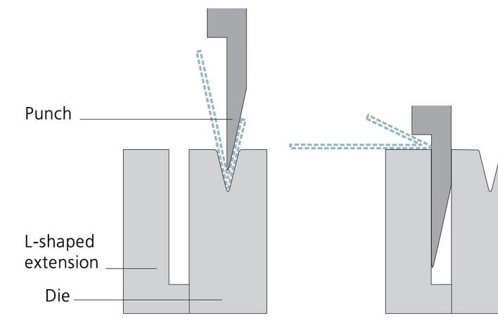
Machine collisions—where the ram, backgauge, tools, or part interfere with each other—are among the most costly and dangerous errors in press brake operation. They often stem from incorrect sequencing, tool mismatches, or misinterpreted backgauge positions.
Beginners must cultivate the habit of running a simulation on the controller before bending. Simulations highlight potential collisions that might not be obvious during programming. Additionally, operators should perform slow-speed tests for new or complex parts, observing the ram and backgauge movements carefully.
Another essential habit is ensuring that long parts do not hit the backgauge during rotation. When a part requires flipping or turning between bends, the operator should visualize how the part moves through space before performing the motion. This prevents accidental impacts that can bend backgauge fingers or damage the entire assembly.
Collision prevention is not only about protecting the machine but also about safeguarding operators. A collision at high force can send metal flying or cause sudden machine movement. Developing thoughtful work habits eliminates these dangers.
Safety is closely linked to efficiency. Operators who work calmly and methodically make fewer mistakes, produce more consistent parts, and maintain safer working conditions. Several best practices help beginners transition into effective operators:
Develop repeatable motions. Experienced operators place their hands consistently, load the sheet the same way each time, and verify seating against the backgauge before bending. Repetition builds muscle memory that reduces errors.
Check parts at regular intervals. Even in stable production conditions, factors such as hydraulic temperature, tool wear, and material variations influence bending results. Routine checks catch small deviations early.
Communicate during teamwork. When operating with a partner, especially for large parts, clear verbal communication ensures synchronized movement and avoids unexpected actions.
Clean the workspace. Removing scrap, dust, and unused tools from the area prevents slips, scratches, and operational interference.
End the shift responsibly. Wiping tools, lowering the ram slightly for safety, and shutting down the hydraulic system properly prolong the machine’s lifespan.
These practices form the backbone of professional press brake operation and help beginners grow into dependable operators.
Operating a CNC press brake is a skill that blends mechanical understanding, careful observation, and practical experience. For beginners, the learning journey can seem lengthy, but each stage builds competence and confidence. Understanding machine components provides the foundation for recognizing how the press brake works as a coordinated system. Learning bending fundamentals clarifies how materials behave under stress and why angles depend on more than programmed values.
Mastering the controller teaches beginners to think logically and structure programs that guide the machine effectively. The step-by-step workflow transforms theoretical knowledge into practical action, allowing new operators to produce accurate parts consistently. Troubleshooting then becomes a natural extension of this learning—an opportunity to refine understanding and improve skill rather than a source of frustration.
Finally, safety binds the entire profession together. Safe operation is not optional; it is the core principle that ensures productivity, consistency, and personal well-being in every fabrication environment. By developing strong safety habits, beginners prepare themselves for long-term success.
With the knowledge presented in this guide, new operators can approach the CNC press brake with confidence. They gain not only the ability to bend metal accurately but also the insight needed to grow into experienced, capable, and dependable professionals in the sheet-metal fabrication industry.
A CNC press brake is a special machine that bends flat sheet metal into different shapes. It uses a computer to control how deep and at what angle the metal is bent, which makes it easier and more accurate than doing it by hand.
Understanding how to use a CNC press brake properly helps beginners ensure their work is safe and accurate. It prepares operators to recognize when things go wrong, which allows them to fix issues before they create bigger problems, keeping everyone safe.
Before operating a CNC press brake, beginners should understand the machine’s parts, how bending works, and basic safety rules. This knowledge will help them recognize how to make adjustments and avoid mistakes during the bending process.
Safety devices like light curtains are designed to protect operators. They create an invisible barrier; if anything passes through it while the machine is operating, the machine stops immediately. Understanding these safety measures is crucial for preventing accidents.
Common errors include bending angles that are too tight or too loose. Beginners should check the settings and adjust the ram depth. If an angle varies across the part, it may be due to crowning or uneven material thickness, which requires careful adjustment.
To check if your parts are correct, you should measure both the angle and the length of the flanges frequently during production. Look for consistency by measuring multiple points, not just one area, and make adjustments as necessary.
The backgauge assists by positioning the sheet metal correctly for each bend. It makes sure that the metal is at the exact distance needed to achieve the right flange length when bending. Learning how to use it properly is key for precise bends.
Springback is when the metal tries to return to its original shape after bending, which can change the final angle. Knowing how much springback to expect helps beginners adjust their settings accurately to achieve the correct bend.
Before starting the CNC press brake, always check that safety devices are functional, all tools are installed correctly, and the program reflects the right material and settings. This ensures safe operation and accurate bends.
To work efficiently, develop consistent motions, check parts regularly, and keep your workspace clean. Communicating with team members during operations can also help to maintain safety and smooth workflows.