Newsletter Subscribe
Enter your email address below and subscribe to our newsletter
Enter your email address below and subscribe to our newsletter
All voices matter

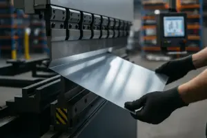
Setting up a press brake for the first time is both exciting and intimidating. Although modern CNC press brakes automate many steps, the quality of a bend still depends on how well the machine, tooling, and material are prepared before the first stroke. A correct setup does far more than ensure the requested angle; it affects tool life, machine accuracy, operator safety, production speed, and long-term consistency. In factories where multiple operators share a single machine, a correct setup routine also establishes a common workflow that reduces human error and ensures predictable results across shifts.
A well-executed press brake setup serves as the foundation for every bending project. It aligns the machine’s mechanical components with material characteristics and part specifications, enabling operators to achieve precision from the very first bend. When the setup process is rushed or incomplete, operators often encounter angle inconsistencies, twisted parts, unexpected springback, excessive crowning adjustments, and tool wear that shortens the life of the punches and dies. This guide explains not only the steps but also the reasoning behind them, giving beginners a practical understanding of how to prepare a press brake safely and correctly.
Before touching any tooling or loading material, new operators must understand the core structure of the press brake. Even highly advanced CNC systems follow the same mechanical principles. Recognizing how the ram, bed, backgauge, and hydraulic or servo-driven systems work creates a mental model that helps operators diagnose issues later. Many accidents occur not because operators ignore rules, but because they misunderstand how the machine reacts to force, speed, or tooling alignment.
The press brake applies bending force through a downward-moving ram. This ram must travel in a straight and stable path for the bend angle to remain consistent. Any misunderstanding about ram guidance, Y1/Y2 synchronization, or upper beam deflection will affect the setup accuracy. Manufacturers like AMADA, TRUMPF, and Bystronic publish machine-specific manuals, and consulting these documents ensures that operators understand the characteristics of the specific model they are working with.
(Reference: https://www.bystronic.com/global/en/products/pressbrakes )
A proper press brake setup requires understanding several essential components, each influencing the final bend:
Understanding these parts ensures that every adjustment made during setup has a clear purpose rather than being guesswork.
Safety is the foundation of every press brake setup, especially for first-time users. A press brake can easily apply forces exceeding 100 tons, capable of crushing metal and human limbs alike. Operators must understand safeguards such as:
A key principle is to always maintain full awareness of hand position and never attempt to stabilize the sheet too close to the tool area. Even experienced operators rely on proper preparation and safe handling practices rather than reflexes.
A successful setup begins before any interaction with the machine itself. The operator must ensure that the surrounding workspace is clean, organized, and completely free from loose parts, metal offcuts, tools, or packaging that could obstruct machine movement or become hazardous during bending. Sheet metal edges can be sharp, and even small pieces of debris can create slip risks or interfere with foot pedal operation. A clean, unobstructed floor also allows lifting equipment and material carts to move smoothly without snagging, reducing the likelihood of accidents during setup.
When a press brake is started from cold conditions—especially in winter or low-temperature workshops—the hydraulic system requires a short warm-up phase. Hydraulic oil viscosity affects ram movement accuracy, braking behavior, and the synchronization between the Y1 and Y2 cylinders. Operating the machine before the oil stabilizes can lead to inconsistent angles, slower response from valves, and drifting in the Y-axis during initial bends.
A proper warm-up routine recommended by most manufacturers includes:
This routine typically takes 2–5 minutes, depending on ambient temperature. Only after the system is fully stabilized should test bends be performed.
(General hydraulic reference: https://www.hydraulicspneumatics.com/technology/hydraulic-fluids/article/21884086/oil-viscosity-guide )
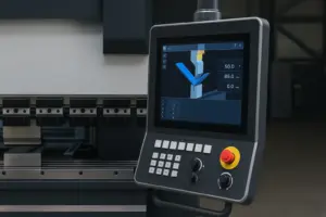
Before starting any production setup, the operator must confirm that all essential machine calibrations are correct. These include:
A misaligned ram can cause uneven bend angles between the left and right sides, producing twisting or tapered parts that are difficult to correct later. Many CNC press brakes automatically perform homing and synchronization at startup, but operators should visually verify the ram’s first few free strokes to ensure smooth, parallel movement.
If the controller provides a dedicated calibration or homing function (common in Delem DA-66T, Cybelec ModEva, and ESA systems), running it ensures that all axes return to their precise reference points before tooling installation begins.
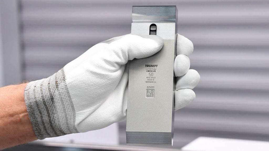
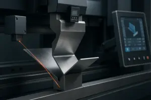
Tooling selection heavily influences the quality of the bend. Beginners often underestimate the importance of die opening size, punch radius, and tooling material. Incorrect tooling reduces accuracy and increases required tonnage, potentially damaging the machine.
Standard tooling types include:
Using precision-ground punches and dies reduces variability and speeds up setup, particularly on CNC press brakes.
A widely accepted rule for air bending is:
V-opening ≈ 6–8 × material thickness
For example, a 3mm mild steel sheet should pair with an 18–24mm die opening.
A smaller V-opening increases tonnage and sharpens the bend radius, risking cracks. A larger V-opening reduces accuracy due to excessive sheet float. Engineering tables from tooling manufacturers such as WILA offer detailed tonnage charts.
(Reference: https://www.wilausa.com )
Punch radius affects both material flow and expected springback. Common choices include:
Bend radius should closely match the punch radius during air bending. A mismatch increases springback and produces irregular angles.
Tooling wear influences angle accuracy more than beginners realize. Even microscopic damage affects how the metal contacts the punch and die. Before setup, operators should check:
Many factories record tooling maintenance logs to track lifespan and avoid unexpected failures.
Dust, oil residue, or metal chips between the tooling and clamp reduce alignment accuracy. Even 0.1 mm of debris creates noticeable bending errors. Operators must thoroughly wipe the tool seat surface with a clean cloth and apply a thin layer of machine oil to prevent corrosion.
The lower die must sit perfectly centered along the bed. Many CNC press brakes include automatic die clamping systems, but manual clamping requires careful tightening from both sides to avoid a tilt. Operators should visually confirm die height uniformity along the entire length.
When using segmented dies, the operator must ensure each segment is flush. A single misaligned segment can ruin the entire part.
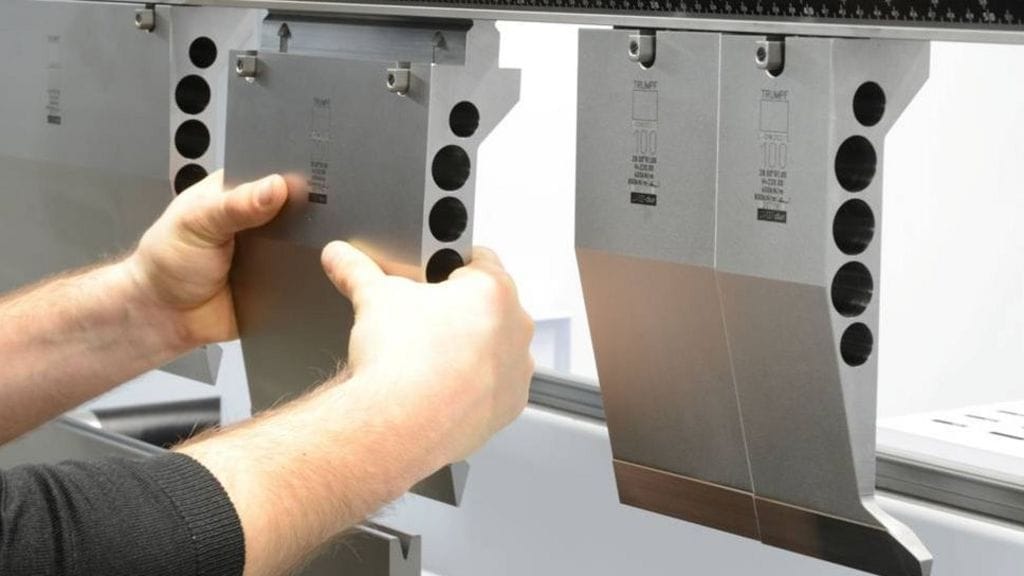
Punch installation follows similar procedures. For manual clamps, the punch must rest firmly and straight in the clamp groove before tightening. Even with automatic clamps, beginners must confirm that the upper tool has no sideways movement.
Gooseneck punches must also be positioned to avoid tool collision with part geometry during bending.
Tooling must align within ±0.03 mm on high-precision CNC machines. Operators can check alignment by:
Misalignment causes uneven angle results, sheet twisting, and crowning compensation errors later in the setup.
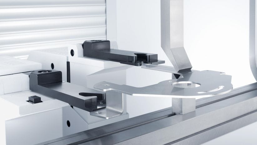
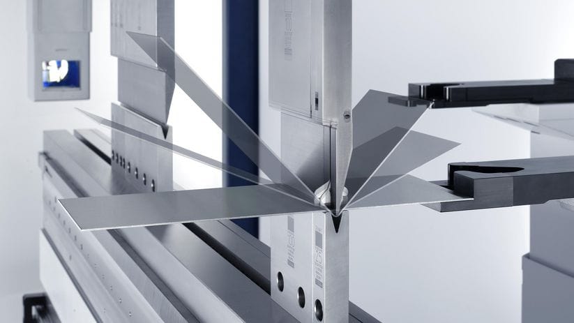
The backgauge is the guiding system that positions the sheet accurately. Bending quality depends as much on backgauge precision as on tooling alignment. Any error in backgauge X-position results in incorrect flange lengths, which can ruin the entire part even if the angle is perfect.
Begin by entering the target flange length into the CNC controller. Before running any stroke, operators must manually verify the backgauge movement for smoothness and ensure no leftover material blocks its path. Many backgauges include fingers with replaceable pads that must be clean and free from wear.
When measuring distances, always confirm whether the program references the inside or outside dimension of the part, as different factories follow different standards.
If the sheet thickness or flange height varies, the R-axis must be adjusted to allow the part to make stable contact with the gauge finger. Too low, and the sheet may slip. Too high, and the sheet may ride over the finger or fail to reach a stable stop point.
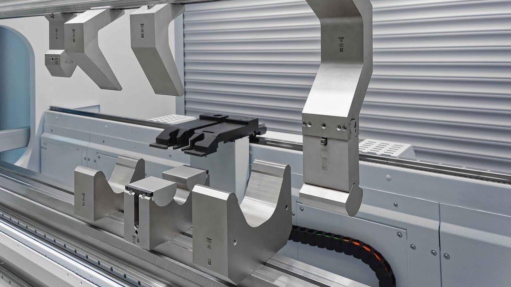
Advanced machines include Z1/Z2 or X1/X2 axes that move independently left and right. These are essential for asymmetrical parts, tapered bends, or multi-station tooling setups. Beginners should update the CNC program to define each axis movement carefully and verify visually before running the machine.
Material behaves differently during bending due to yield strength, thickness tolerances, and elasticity. Springback values vary widely between materials:
Accurate material data ensures the CNC can calculate correct Y-axis depth and crowning values.
The operator must enter—or select from the library—the following parameters:
Actual sheet thickness often differs from nominal thickness by ±0.05–0.15 mm, and this difference significantly affects the angle. Always measure using a caliper before setup.
CNC systems apply overbending to counteract springback. The controller may offer:
Beginners should run several test bends to fine-tune these values.
When bending long sheets, the press brake bed naturally deflects. Without compensation, angle results are tighter near the sides and looser in the middle. Crowning systems counteract this deflection through mechanical wedges or hydraulic cylinders.
Mechanical Crowning
Uses adjustable wedges to raise the die center. Entry-level machines use this method due to its simplicity.
Hydraulic Crowning
Uses oil pressure under the die bed to dynamically adjust deflection. High-end CNC brakes automate this based on real-time calculations.
The CNC controller typically calculates crowning automatically using material thickness, bend length, and tonnage. However, operators should still verify by checking angle consistency along the bend:
Always make adjustments in small increments.
Before loading a sheet, the operator runs a dry cycle:
Only after verifying correct motion should the first sheet be loaded.
Insert the sheet, ensuring it fully contacts the backgauge. Press the foot pedal slowly, using the low-speed approach mode. Observe how the material enters the V-opening and whether it stays flush against the punch.
Use a digital protractor to measure both ends and the center of the sheet. Differences greater than 0.5° require adjustments.
Understanding how each machine axis interacts with material behavior is the key to mastering setup.
Once the test bends meet specifications, save the program and archive the settings. Professional factories often store:
This ensures repeatability for future batches.
Factories with multiple operators rely on setup sheets to maintain uniformity. A typical setup sheet includes:
Setup sheets reduce training time and ensure consistent quality across shifts.
Before running a full batch, the operator must recheck:
These final checks prevent accidents and ensure long-term machine health.
Setting up a press brake for the first time is fundamentally about learning how the machine, tooling, and material interact. While CNC automation simplifies many tasks, the operator’s understanding of principles like crowning, springback, tooling selection, and backgauge positioning determines the overall success. By following a systematic process—preparing the workspace, selecting the right tooling, configuring material parameters, adjusting crowning, and verifying performance through test bends—beginners can achieve professional-level accuracy from day one. With repetition, these steps become instinctive and form the foundation of efficient and safe sheet metal bending.