Newsletter Subscribe
Enter your email address below and subscribe to our newsletter
Enter your email address below and subscribe to our newsletter
All voices matter
Understanding how a press brake works is one of the most essential foundations in modern sheet metal fabrication. Whether you are an operator learning the basics, an engineer improving production processes, or a factory owner comparing different bending technologies, the principles behind a press brake determine every outcome—from angle accuracy to product consistency and long-term machine performance. Although press brakes are widely used across industries like automotive, HVAC, aerospace, and electrical enclosures, many people only see the final bent part without understanding the physics and engineering behind the process.
This article provides a comprehensive yet beginner-friendly explanation of press brake working principles, combining both fundamental theory and real-world industrial experience. You will learn what a press brake is, how its individual components operate, how bending forces are calculated, and why accuracy depends on a combination of materials, tooling choices, and machine technology. To enhance authority and technical depth, references from global industry leaders such as AMADA, LVD, TRUMPF, Bystronic, and tooling specialists like WILA are included throughout the article. For standards-based readers, relevant international specifications—for example, the ISO 7438 bend test standard—are also mentioned to reinforce reliability and accuracy.
As you move through each chapter, you will see how different press brake types work, how CNC systems enhance precision, and why modern machines rely on sensors, servo drives, and software optimization. The goal is not simply to memorize the machine’s functions but to understand how the entire bending ecosystem interacts. With this knowledge, operators can predict bending behavior more accurately, engineers can design more efficient workflows, and business owners can make smarter investment decisions. By the end of this guide, the working logic of a press brake will become intuitive rather than mysterious.
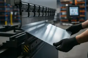
A press brake is a machine tool designed to bend sheet metal into precise shapes by applying force through a punch and die set. Although the machine appears simple at first glance, it represents decades of engineering evolution in mechanical design, hydraulic control, and digital automation. At its core, the press brake uses downward force from a ram to press the sheet metal into a V-shaped die, creating bends of various angles and dimensions. This forming method makes it possible to produce everything from small brackets and electrical cabinet parts to large automotive chassis components.
The term press brake originated from early mechanical versions, where metal was “broken” or “bent” along a straight line. Modern press brakes are far more advanced, capable of multi-axis control, extremely high accuracy, and automated production workflows. Their purpose remains the same: to form sheet metal with repeatable precision. The machine must not only deliver sufficient force but also maintain synchronized motion, ensure tooling alignment, and compensate for material variations. Manufacturers such as TRUMPF provide detailed technical explanations of bending processes, reinforcing the importance of machine design in achieving accuracy (Reference: https://www.trumpf.com/).
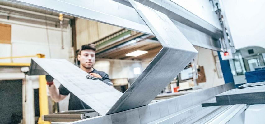
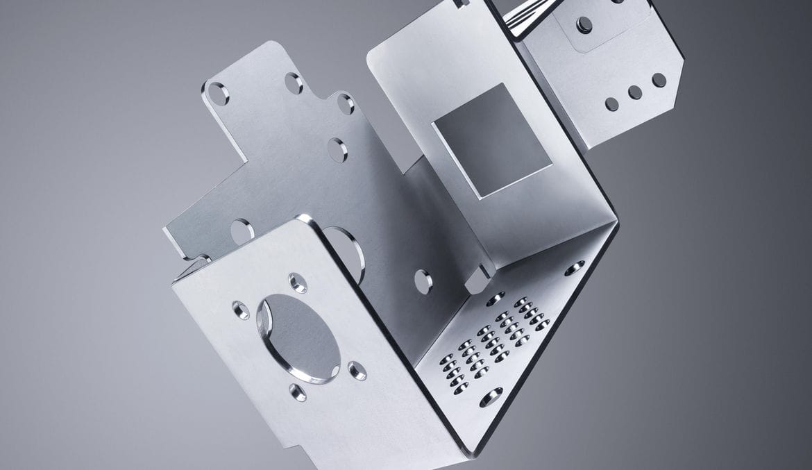
In modern manufacturing environments, the press brake is indispensable because it transforms flat sheet metal into functional three-dimensional parts. Everything from enclosures, doors, and housings to structural components depends on accurate bending. Factories prefer press brakes because they offer flexibility—one machine can handle hundreds of part types by simply changing tools or modifying CNC programs. This adaptability makes them essential for batch production, prototyping, and fully automated smart manufacturing lines.
Press brakes also bridge the gap between design and final product, allowing engineers to convert CAD drawings into finished parts with predictable tolerances. The bending process affects downstream operations such as welding, assembly, and finishing, so angle accuracy and consistency are critical. Global brands like AMADA highlight how bending quality directly affects overall production efficiency (Reference: https://www.amada.com/).
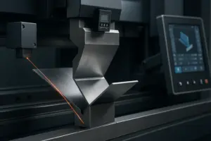
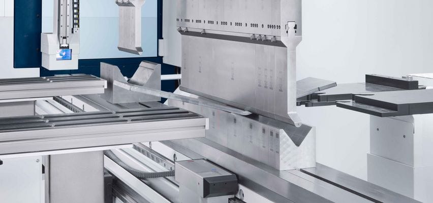
A press brake consists of multiple coordinated systems, each playing an important role in how the machine works. The main frame provides rigidity, ensuring that bending forces do not distort the machine structure. A heavy-duty frame is essential for maintaining parallelism between the ram and bed, especially during full-length bending operations. Manufacturers like LVD emphasize frame stiffness as one of the key factors influencing precision and long-term durability (Reference: https://www.lvdgroup.com/).
The ram, powered by hydraulic cylinders, electric servo motors, or mechanical flywheels, delivers the downward force required for bending. The punch attaches to the ram and forms the upper part of the tooling, while the die, mounted on the lower table, forms the lower contact surface. The backgauge positions the sheet metal at the correct depth, ensuring each bend dimension matches the design. Modern machines often feature multi-axis backgauges that adjust height, depth, and angle automatically.
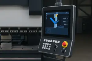
Another critical component is the CNC controller, which manages machine motion, angle calculation, crowning compensation, and safety functions. Without the CNC system, achieving consistent angles across varying materials would require much more manual adjustment. Today’s controllers integrate bending databases, material libraries, and real-time sensors, enabling even inexperienced operators to produce high-quality parts.
Understanding the working principles of a press brake is essential because every bending result—angle accuracy, straightness, and structural integrity—comes from how the machine applies and controls force. Although modern press brakes incorporate advanced CNC systems, servo motors, and digital sensors, their fundamental working logic still follows the same mechanical and physical principles established decades ago. In this chapter, we will break down those principles into clear, accessible explanations, ensuring that beginners and professionals can both understand how each element contributes to a precise bend.
The term press brake working principles refers not only to how the ram moves but also to how materials deform, how tooling interacts with sheet metal, and how the machine compensates for deflection, springback, and material inconsistencies. Global manufacturers such as Bystronic, TRUMPF, and LVD publish detailed guides on these principles because they form the foundation for safe operation, accurate bending, and productivity optimization (Reference: https://www.bystronic.com/).
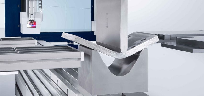
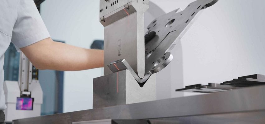
The central mechanism of a press brake involves the controlled downward motion of the ram pressing the punch into the die. During this process, the sheet metal undergoes both compression and tension forces. The upper punch forces the metal into the V-shaped lower die opening, causing the material to plastically deform. This deformation results in a permanent bend—meaning the metal retains its shape after the force is removed.
While this appears simple, precise bending depends on controlling ram speed, approach distance, tonnage, penetration depth, and timing. CNC systems regulate Y1 and Y2 cylinders (in hydraulic machines), ensuring that both sides of the ram move in perfect synchronization. Even a small difference of 0.01 mm can affect the resulting angle. This is why servo-hydraulic valves and linear encoders are critical components on higher-end models.
Manufacturers such as TRUMPF highlight how servo-controlled systems help maintain consistent ram movement even under varying loads or long bending lengths (Reference: https://www.trumpf.com/). This consistency enables operators to achieve repeated accuracy even across large production runs.
When a sheet of metal is bent, the material fibers on the inside radius of the bend are compressed, while the fibers on the outside radius are stretched. Between these regions lies a theoretical layer called the neutral axis, which experiences neither tension nor compression. Understanding this concept is vital because it determines how the metal behaves during bending and how much force is required.
The bend allowance and bend deduction in fabrication drawings are calculated based on the position of the neutral axis. Its location depends on material thickness, hardness, and the radius of the punch tip. Harder materials push the neutral axis outward, meaning they require more force and create greater springback. Softer materials deform more easily and require lower tonnage.
This physical behavior is not just theoretical—it directly affects accuracy. For example, when bending stainless steel, the neutral axis shifts more compared to mild steel due to greater tensile strength. Such details explain why material charts and bending calculators are commonly used in press brake programming.
Organizations such as ASM International and ISO (International Organization for Standardization) provide engineering references on material behavior during deformation (Reference: https://www.iso.org/standard/16268.html – ISO 7438 Bend Test).
Springback is one of the most important—and unavoidable—phenomena in press brake bending. After the bending force is removed, the metal naturally attempts to return to its original flat shape, causing the angle to open slightly. This behavior occurs because the outer fibers, which were stretched during bending, pull back toward equilibrium.
The degree of springback depends on various factors:
High-strength materials such as stainless steel and aluminum exhibit more springback due to their elastic properties. To compensate, CNC controllers automatically calculate overbend angles, causing the ram to penetrate slightly deeper into the die to achieve the desired final angle. Modern machines apply built-in angle correction algorithms, using databases of material behavior.
Some advanced systems—such as LVD’s Easy-Form® Laser—measure the angle in real time and adjust the ram position during the bend (Reference: https://www.lvdgroup.com/). This allows the machine to correct springback instantly, even for materials with significant variability.
Angle accuracy depends on more than just machine quality. It is a combined result of material behavior, tooling condition, machine calibration, and operator setup. Several key factors influence accuracy:
Even sheets from the same batch can vary slightly in thickness or hardness. These differences alter bending force requirements and springback behavior. This is why many factories use test bends before full production.
Worn punches or dies produce inconsistent angles. Misalignment between upper and lower tooling can cause twists, tapering, or uneven bends. Tooling manufacturers such as WILA emphasize strict tolerance control and hardened surfaces to ensure reliable results (Reference: https://www.wila.com/).
All press brakes deflect under load—meaning the ram slightly bows upward while the table bows downward. Crowning systems counteract this deflection, ensuring the bend angle remains consistent along the entire length. Hydraulic and mechanical crowning systems automatically adjust pressure or mechanical wedges to achieve this compensation.
Accurate control of penetration depth is essential. Even a 0.1 mm difference can change the bend angle by several degrees depending on die geometry. High-end machines use optical encoders and servo valves to maintain micrometer-level accuracy.
The backgauge ensures correct flange length. If it is misaligned or improperly calibrated, even a perfect bend angle will produce incorrect part dimensions.
These factors together define how closely the final bend matches the programmed value. With proper training, calibration, and high-quality equipment, it is possible to achieve angle tolerances of ±0.2° or better—a standard commonly promoted by premium brands such as Bystronic.
Press brakes have evolved dramatically over the past century, transitioning from simple mechanical devices to highly sophisticated CNC-controlled systems. Although all press brakes perform the same basic function—bending sheet metal—the internal mechanisms, control systems, efficiency, and force generation methods differ significantly among the main types. Understanding these differences is essential for selecting the right machine for a factory’s production needs and for understanding how each machine’s working principles influence performance, accuracy, and maintenance requirements.
In this chapter, we examine five major categories of press brakes: mechanical, hydraulic, CNC hydraulic synchronized, electric/servo, and hybrid press brakes. Each type has distinct advantages and limitations rooted in its mechanical design. Global manufacturers such as AMADA, TRUMPF, Bystronic, and LVD offer detailed explanations of these designs because selecting the correct press brake directly impacts production speed, energy consumption, tooling lifespan, and achievable tolerances (Reference: https://www.amada.com/).
Mechanical press brakes were once the dominant type in metal fabrication, especially before hydraulic technology became widely accessible. A mechanical press brake uses a flywheel powered by an electric motor. When the operator engages the clutch, the stored kinetic energy in the flywheel transfers to the ram through a crank mechanism, forcing it downward.
This system produces a powerful, consistent motion, but the ram movement is fixed and follows the mechanical cycle determined by the crankshaft. Because of this, mechanical press brakes cannot easily adjust ram speed or stopping points, limiting precision and making them less suitable for modern bending requirements.
Mechanical press brakes tend to be fast and relatively simple to maintain, but they lack the safety features and fine control needed for complex jobs. Their fixed stroke also makes them unsuitable for delicate materials or intricate forms that require precise slow-speed bending. For safety reasons and stricter machine control standards, many countries now restrict the use of older mechanical models, encouraging factories to upgrade to hydraulic or CNC versions.
Despite their age, mechanical press brakes remain valuable in certain high-speed, single-angle production environments. However, they cannot match the flexibility or accuracy of modern CNC-controlled hydraulic or electric systems.
Hydraulic press brakes replaced mechanical models as the global industry standard because they offer significantly greater control over ram movement. Instead of relying on a flywheel, hydraulic press brakes use one or more hydraulic cylinders to generate force. By controlling oil flow through proportional valves, the ram can move at variable speeds and stop at any position within its stroke.
Hydraulic systems provide a smoother, more controlled motion, making it possible to perform air bending, bottom bending, and coining with high accuracy. The hydraulic pressure can be monitored and adjusted, ensuring consistent force even when bending long parts. This flexibility is critical for industries like HVAC, automotive, and enclosure manufacturing.
One of the major advantages of hydraulic press brakes is their safety. When the operator releases the foot pedal, oil flow stops, and the ram freezes in place. This feature, combined with modern safety systems such as LazerSafe and DSP, makes hydraulic machines significantly safer than older mechanical types (Reference: https://www.lazersafe.com/).
However, hydraulic machines require regular maintenance, including oil changes, seal inspections, and valve calibration. Temperature fluctuations can also affect oil viscosity, causing variations in ram speed or angle consistency unless warm-up cycles are performed.
Despite these minor challenges, hydraulic press brakes remain the most commonly used type worldwide due to their balance of power, accuracy, and affordability.
CNC hydraulic synchronized press brakes represent the modern evolution of hydraulic bending technology. Unlike conventional hydraulic machines where both cylinders operate in unison but without digital correction, a synchronized press brake uses Y1 and Y2 servo-hydraulic control, allowing each cylinder to move independently under CNC supervision.
This means the machine constantly monitors and adjusts the position of both cylinders using linear encoders mounted on the frame. Even if the load is uneven across the bending length, the CNC ensures both sides of the ram stay perfectly synchronized to within fractions of a millimeter.
The benefits of CNC synchronized press brakes include:
Independent control of both cylinders ensures extremely tight parallelism between ram and table. Accuracy improves dramatically, often reaching ±0.2° with proper tooling.
The machine can automatically adjust for variations in material thickness or hardness, reducing manual corrections.
CNC hydraulic machines typically include multi-axis backgauges (X, R, Z1, Z2, X1, X2) that move automatically according to bending programs. This enables complex part sequences and highly consistent production.
These machines allow offline programming, angle correction algorithms, 3D simulation, material libraries, and setup instructions directly on the controller.
Brands such as Bystronic and LVD use advanced hydraulic synchronization systems to deliver exceptional performance in industrial environments (Reference: https://www.lvdgroup.com/).
CNC hydraulic synchronized machines remain the most popular choice for medium-to-large factories due to their excellent balance of power, control, price, and versatility.
Electric press brakes—often called servo-electric press brakes—use servo motors instead of hydraulic systems to drive the ram. These machines represent one of the most modern innovations in bending technology, offering exceptional energy efficiency, extremely low noise, and precise motion control.
Servo-electric press brakes typically use a belt and pulley system, ball screws, or direct servo drives to translate rotational motion into linear ram movement. Because servo motors offer accurate, repeatable positioning, electric systems achieve outstanding precision, often with tighter tolerances than hydraulic models.
1. Energy Savings
Electric press brakes consume power only when the ram is moving. In contrast, hydraulic machines consume energy continuously to maintain oil pressure.
2. High Precision
Servo drives allow precise control of penetration depth, making them ideal for forming thin materials and achieving consistent results.
3. Cleaner Operation
There is no hydraulic oil, eliminating leaks and reducing maintenance requirements.
4. Rapid Cycling Speed
Electric machines often outperform hydraulic machines in speed-critical applications, particularly in electronics and automotive component manufacturing.
However, electric press brakes typically have lower maximum tonnage compared to hydraulic models. This makes them more suitable for thin-to-medium materials rather than heavy plate bending. Premium manufacturers like AMADA and Salvagnini offer advanced servo-electric systems capable of extremely high accuracy (Reference: https://www.amada.com/).
Hybrid press brakes combine the advantages of hydraulic and servo-electric systems. In a hybrid design, servo motors control the hydraulic pressure, significantly reducing oil usage and increasing energy efficiency. The result is a machine that delivers high power like a hydraulic press brake while maintaining the precision and energy savings of servo-electric systems.
Hybrid systems use smaller hydraulic circuits with servo control, providing:
Hybrid press brakes are often found in high-end production environments where consistency, energy savings, and low maintenance are required. Brands such as TRUMPF and Bystronic manufacture hybrid models that focus on smart manufacturing and Industry 4.0 integration (Reference: https://www.trumpf.com/).
These machines bridge the gap between traditional hydraulic machines and cutting-edge servo-electric models, making them suitable for factories that handle a wide range of material thicknesses with demanding accuracy requirements.
Although press brakes vary in design—hydraulic, electric, mechanical, or hybrid—the bending cycle follows a predictable sequence of operations. Understanding this sequence is essential for operators, engineers, and production managers because each stage influences angle accuracy, tool life, and overall productivity. This step-by-step explanation breaks down the real operational workflow inside a press brake, showing how the machine transforms flat sheet metal into a precisely bent part.
This chapter describes the bending process in four clear stages: tooling setup, ram approach, active bending, and decompression/return stroke. The workflow applies to most modern CNC press brakes used in industries such as automotive, aerospace, HVAC, metal furniture, and electrical cabinet production. High-end manufacturers like Bystronic, LVD, and AMADA often demonstrate similar step-by-step cycles in their product documentation (Reference: https://www.bystronic.com/).
The bending process always begins with tooling installation and backgauge configuration. Proper setup ensures that the intended bend angle, radius, and flange dimensions can be achieved reliably.
First, operators select the correct punch and die based on material thickness, bend radius requirements, and bending method (air bend, bottom bend, or coining). The tooling is clamped onto the upper beam and machine bed using manual clamps, hydraulic clamps, or precision quick-change systems. Manufacturers such as WILA offer modern tooling interfaces that ensure perfect alignment and reduce setup time (Reference: https://www.wila.com/).
Once tooling is installed, the backgauge is positioned according to the programmed flange size. In CNC press brakes, this movement is automated, controlled by multiple axes (X, R, Z1, Z2, X1, X2 depending on machine configuration). Multi-axis backgauges allow the machine to perform complex part sequences with different flange lengths and angles.
Accurate setup is crucial: even slight misalignment in tooling or backgauge positioning can cause incorrect dimensions or twisted parts. This first stage ensures the machine is physically prepared for consistent, repeatable bending.
After the material is positioned against the backgauge, the press brake begins the ram approach phase—the rapid downward movement of the upper beam before contact with the sheet metal.
During this stage, the ram travels at a high speed to minimize cycle time. However, as the punch tip nears the top of the material, the CNC system automatically slows the ram to a precise, controlled speed. This transition from rapid descent to controlled descent is essential for accuracy and safety.
Hydraulic machines use proportional valves and servo-hydraulic controls to manage this speed transition. Electric and hybrid machines rely on servo motors for smoother, quieter deceleration. Leading manufacturers such as TRUMPF highlight the importance of approach speed control because inconsistent or overly fast motion can cause minor impacts and angle variation (Reference: https://www.trumpf.com/).
The ram approach phase does not yet apply bending force; instead, it stabilizes the machine’s motion and prepares the system for controlled deformation. The goal is to minimize time while ensuring the ram enters the bending zone with perfect alignment and stability.
This is the heart of the bending process. As the punch contacts the metal and continues its downward motion, the material is forced into the die opening, creating the bend. At this stage, several simultaneous physical and mechanical processes occur:
The inside of the bend undergoes compression, while the outside stretches. The neutral axis shifts depending on material type, thickness, and tooling geometry. This determines bend allowance and influences the final angle.
The CNC calculates the required force using bending formulas, material databases, and punch/die specifications. Hydraulic systems manage tonnage through oil pressure control, while servo-electric machines apply force directly through electric motors.
Advanced systems such as LVD’s Easy-Form® Laser measure the angle during bending and automatically correct ram position in real time (Reference: https://www.lvdgroup.com/).
This eliminates the need for test bends in most cases.
Because every press brake deflects under load, crowning systems counteract the natural bowing of the machine bed. Without crowning, angles would vary between the center and edges of the part. Mechanical wedges or hydraulic cylinders apply the appropriate compensation force.
Depending on the method—air bending, bottom bending, or coining—the punch penetrates to different depths inside the die opening.
During the bending phase, precision control is critical. Even a 0.05–0.1 mm difference in ram penetration can alter the bend angle by 1–2 degrees depending on the die width.
Once the programmed penetration depth is reached, the CNC instructs the machine to stop applying force. At this moment, the ram begins the decompression phase, releasing pressure and allowing the material to stabilize.
As the ram retracts, the metal relaxes slightly, causing springback. CNC programs account for this by overbending the angle so that the final part matches the desired specification. Material databases and angle measurement sensors provide additional correction mechanisms.
After decompression, the ram performs the returning stroke, moving upward at a rapid speed similar to the approach speed used earlier. The material is then repositioned for the next bend, or the operator removes the finished part.
Modern press brakes optimize the return cycle to reduce wasted motion and speed up production. Electric press brakes, for example, are known for exceptionally fast return strokes with low noise and minimal vibration. Manufacturers such as AMADA highlight energy-efficient recovery cycles as a key advantage of their servo-electric models (Reference: https://www.amada.com/).
The completion of the return stroke marks the end of one full bending cycle. When performed sequentially, the machine can execute dozens or even hundreds of bends per part, all while maintaining consistent accuracy and speed.
Modern press brakes owe much of their precision, speed, and versatility to CNC (Computer Numerical Control) technology. While the mechanical structure of the machine defines its basic capabilities, CNC systems elevate the press brake into a highly intelligent, adaptive, and automated bending platform. This chapter explains how CNC controls influence bending accuracy, consistency, and workflow efficiency, and how they interact with mechanical systems to enhance the core press brake working principles.
Leading global brands such as TRUMPF, LVD, Bystronic, and AMADA integrate advanced CNC technology into their machines, enabling real-time corrections, bending simulation, offline programming, and multi-axis automation. These features dramatically reduce operator dependency, minimize setup time, and ensure repeatable results even when bending challenging materials (Reference: https://www.trumpf.com/).
One of the most important advancements in CNC-controlled press brakes is independent Y1 and Y2 axis control, which ensures synchronized motion of the left and right sides of the ram. This synchronization is essential because even slight differences in cylinder position can lead to angled, twisted, or tapered bends.
Y1 and Y2 represent the left and right hydraulic cylinders. In older non-CNC hydraulic machines, both cylinders were mechanically linked and moved together. However, this method could not correct for frame deflection, load imbalance, or material variations.
CNC control allows each cylinder to move independently while staying perfectly synchronized through real-time feedback.
High-resolution linear encoders mounted on the frame continuously measure the ram position with micrometer-level accuracy. The CNC receives this data and adjusts each cylinder accordingly, ensuring parallelism between the ram and the machine bed.
When bending long parts or asymmetric shapes, the load is rarely evenly distributed. Without CNC synchronization, bends would be inconsistent along the length of the sheet.
With Y1/Y2 control, the machine compensates for these variations instantly.
Manufacturers like Bystronic and LVD emphasize the importance of synchronized control in delivering top-tier accuracy (Reference: https://www.lvdgroup.com/).
Every press brake experiences natural deflection under load:
If not corrected, this results in inconsistent angles—sharper at the ends and flatter in the center.
Crowning systems solve this problem by applying controlled counter-deflection.
Hydraulic cylinders beneath the lower table generate upward force proportional to the bending pressure. This compensates for deflection and restores a straight bending line.
Adjustable wedges or cam systems physically alter the bed’s shape to counteract deflection. These mechanisms are set either manually or automatically via CNC.
The CNC calculates the required compensation based on:
This ensures every bend remains consistent from end to end, even during long bending cycles or when operators switch materials.
Companies like WILA offer CNC-controlled crowning with extremely tight tolerances (Reference: https://www.wila.com/).
Advanced CNC systems incorporate angle measurement technologies that monitor the bend during the actual forming process. These real-time systems eliminate the need for trial bends and dramatically increase accuracy for both experienced and inexperienced operators.
Laser sensors project beams across the material to detect angle changes as bending occurs. Systems such as LVD’s Easy-Form® scan the sheet from both sides and provide live feedback to the CNC controller.
Mechanical probes touch the material surface and measure the angle via physical contact. Although slower than laser methods, contact probes remain reliable for thick plates or reflective surfaces.
The CNC automatically adjusts ram penetration depth within milliseconds to achieve the desired final angle. This prevents errors caused by springback, material inconsistency, or slight variations in sheet thickness.
Angle measurement systems have become essential in industries where tolerances are extremely strict, such as aerospace, elevator production, medical equipment, and precision electronics.
In recent years, CNC controls have evolved from simple positioning systems into intelligent assistants capable of learning, predicting, and optimizing the bending process.
AI-based CNC systems are emerging as a key part of the next generation of press brakes. Companies like TRUMPF and Bystronic lead in integrating smart technologies, including automated tool recognition, material sensing, and adaptive bending algorithms (Reference: https://www.bystronic.com/).
AI can detect variations in sheet hardness or thickness and automatically adjust bending parameters without operator intervention.
Machine learning models predict springback before bending begins, reducing cycle time and improving first-bend accuracy.
CNC controls provide step-by-step visual instructions, part simulation, collision detection, and automatic sequencing. This significantly reduces training time for new operators.
Modern CNC systems communicate with:
This transforms the press brake into a fully connected production cell that supports Industry 4.0 initiatives.
AI-enhanced CNC systems represent one of the most important advancements in press brake working principles, pushing bending accuracy and efficiency far beyond traditional human-controlled processes.
Press brake tooling is one of the most influential factors in bending accuracy, machine performance, and part quality. Even the most advanced CNC system cannot compensate for poor tooling selection or worn tools. Tooling determines how force is applied, how the material deforms, how much tonnage is required, and how the final bend angle behaves. In other words, the press brake working principles rely heavily on the interaction between punch, die, and sheet metal.
This chapter explores how tooling geometry, V-opening size, material characteristics, and bending methods shape the outcome of every bend. Manufacturers such as WILA, Rolleri, and Wilson Tool provide extensive documentation emphasizing that correct tooling selection is essential for achieving consistent, repeatable results (Reference: https://www.wila.com/).
Every press brake uses a combination of upper tools (punches) and lower tools (dies). The shape, angle, and radius of these tools define the bending radius and influence how much force is required.
Common punch shapes include:
The punch tip radius has a direct impact on the inside radius of the finished bend. A larger punch radius produces a smoother and more gradual bend, reducing material stress.
Dies vary widely depending on the bending method and material thickness. V-dies are the most common, with opening widths ranging from a few millimeters to hundreds of millimeters.
Specialized dies include:
Die angle also influences springback and bending force. A 90° die, a 60° die, and an acute die all provide different bending behaviors, even with the same material.
Tooling must be hardened to ensure long service life. Premium brands use:
Quality tooling reduces wear, maintains angle consistency, and prevents surface defects on the bent part.
One of the fundamental principles of press brake operation is the relationship between V-opening size and required bending force. The wider the die opening, the less force is needed; the narrower the die, the more force is required.
The widely used bending force formula is:
Where:
As a rule of thumb:
V-opening ≈ 8 × material thickness (mild steel)
V-opening ≈ 10 × material thickness (stainless steel)
Using a too-small V-opening causes excessive tonnage and risks damaging both tools and the machine.
Using a too-large opening reduces angle accuracy and increases springback.
Smaller V-openings provide sharper bends but cause more material stress and springback. Larger V-openings reduce accuracy for small flanges or tight radii.
Tooling guides from Wilson Tool and engineering references from WILA emphasize that improper V-opening selection is one of the top causes of angle inconsistency (Reference: https://www.wilsontool.com/).
Different materials behave differently during bending. Understanding material properties ensures the correct tooling is selected for each job.
Tool manufacturers often provide material-specific charts to help operators determine the correct punch tip radius and V-opening size.
The method of bending dramatically changes the working principles and tooling requirements.
The punch does not fully press the sheet into the bottom of the die.
Instead, the punch penetrates only partially into the V-opening.
Advantages:
Role of Tooling:
Tool geometry strongly influences angle accuracy because penetration depth determines angle.
The punch forces the sheet to contact both sides of the V-die opening.
Advantages:
Tooling Requirements:
Precise punch/die alignment is essential. Worn tools produce angle variation.
The punch penetrates fully into the die cavity, imprinting the material.
Advantages:
Disadvantages:
Because of the high stress, manufacturers recommend using hardened coining tools and avoiding coining for high-strength steels unless necessary.
Press brakes are among the most powerful machines in any sheet metal production facility, capable of applying tens or even hundreds of tons of force. Because the bending zone involves a moving ram, tooling, and metal sheets with sharp edges, safety is not optional—it is fundamental. Modern press brakes integrate multiple safety layers, including mechanical safeguards, optical protection systems, hydraulic interlocks, and CNC-based monitoring technologies. Together, these systems ensure that operators can work efficiently while minimizing the risk of injury or machine damage.
In this chapter, we explore how press brake safety systems work, how they align with global safety standards, and how they reinforce the machine’s fundamental working principles. Leading safety technology providers such as LazerSafe, DSP, and SICK develop advanced press brake protection systems that comply with international regulations such as EN 12622, ISO 13849-1, and OSHA standards (Reference: https://www.lazersafe.com/).
Mechanical safety features form the foundation of every press brake’s protection system. They ensure that the machine’s physical components operate within safe parameters.
Older mechanical press brakes required two-hand control stations to activate the ram, ensuring the operator’s hands were away from the bending zone. While largely outdated in modern CNC systems, this principle remains important for understanding historical safety design.
Some areas of the machine—such as behind the ram, side panels, and electrical cabinets—are protected by fixed guards. These prevent accidental contact with moving components, drive systems, or high-voltage equipment.
Most press brakes have interlocked rear doors. Opening these doors immediately stops the machine’s motion. Interlocks ensure that maintenance staff cannot access the hydraulic or electrical systems without disabling the machine safely.
Large, easily accessible emergency stop buttons are located on both sides of the machine and on the control panel. Pressing an E-stop halts all motion and depressurizes the hydraulic system to prevent unintended ram movement.
Mechanical safety features work in combination with electrical and optical systems to create multi-layer protection.
Modern press brakes rely heavily on laser safety systems because they allow fast, accurate bending without compromising safety. These systems monitor the bending zone and stop the ram immediately if a hand or object enters the hazardous area.
Laser optical systems create an invisible protection curtain a few millimeters below the punch tip. When an object—such as a finger—breaks this laser field, the CNC instantly stops ram motion.
The response time is measured in milliseconds, ensuring high safety even during rapid approach speeds.
The laser transmitter follows the punch as it moves downward, protecting the operator while still allowing hands close enough to manipulate the material.
Brands like LazerSafe LZS-005 support high-speed bending while maintaining EN 12622 Category 4 safety compliance.
These systems dynamically adjust protection distance based on ram speed, tool height, and bending mode.
Laser safety systems communicate continuously with the CNC controller, ensuring:
This intelligent integration makes modern press brakes safer than any previous generation of sheet metal machinery.
Beyond mechanical and optical systems, press brakes incorporate multiple electronic and hydraulic protections to ensure the machine operates only under safe conditions.
Hydraulic machines use specially designed valves and pressure monitoring systems:
These systems prevent unintended downward motion, even if there is a power failure or hydraulic leak.
CNC press brakes use sensors and logic circuits that verify safe operating conditions:
If any system detects abnormal behavior, the CNC halts all motion instantly.
During setup or tool alignment, the CNC automatically limits ram speed.
This is a critical EN 12622 safety requirement.
Operators cannot accidentally trigger high-speed bending while their hands are near the tooling.
Press brakes use dual-stage foot pedals:
This two-step control prevents sudden, unexpected ram movements.
Even experienced fabricators often have questions about press brake behavior, bending accuracy, tonnage calculation, springback, and CNC functions. In this chapter, we address the most common questions operators, engineers, and buyers ask about how a press brake works. Each explanation is written in a clear, accessible format, while still supported by authoritative technical knowledge from industry-leading manufacturers such as AMADA, LVD, Bystronic, TRUMPF, and WILA.
This Q&A section helps clarify not just what happens during bending, but why it happens—giving users a deeper understanding of the machine’s working principles.
Different materials bend differently because of variations in tensile strength, elasticity, hardness, and grain direction. For example, stainless steel has a higher tensile strength than mild steel, so it requires more force to bend and generates more springback. Aluminum, though softer, has high elasticity, which also increases springback.
Organizations like ASM International provide detailed engineering data on material properties and deformation (Reference: https://www.asminternational.org/).
Springback occurs because metal behaves elastically before it reaches plastic deformation. When the bending force is removed, the material tries to return to its original shape, causing the angle to open up slightly.
CNC systems compensate automatically by applying overbend, ensuring that the final part matches the intended angle. Advanced sensors like LVD’s Easy-Form® Laser correct springback during the bending process in real time (Reference: https://www.lvdgroup.com/).
Modern CNC controllers calculate ram penetration depth using:
The controller uses built-in bending formulas to determine the required penetration depth. For example, air bending requires precise control because a small change in penetration—sometimes as little as 0.1 mm—can alter the angle by several degrees.
CNC systems also adjust the depth automatically based on:
Brands like AMADA and Bystronic offer CNC systems with very high positioning accuracy, often within ±0.01 mm (Reference: https://www.amada.com/).
Inconsistent angles across long parts typically occur due to machine deflection, material thickness variation, or tooling wear.
Crowning systems and CNC synchronization correct most of these problems.
Tonnage depends on:
A commonly used formula for air bending mild steel is:
Where t = sheet thickness and V = die opening.
Press brake manufacturers often provide tonnage charts.
WILA and Wilson Tool offer online calculators to determine required force (Reference: https://www.wilsontool.com/).
These three methods differ in force, accuracy, and material deformation.
Understanding these methods helps operators choose the best approach for the required tolerance.
Cracking occurs when the material exceeds its elastic limit or when the inside bend radius is too small for the material’s properties.
High-strength steels and aluminum alloys are especially prone to cracking if minimum bend radii are not respected.
Sheet metal has a grain structure resulting from rolling during manufacturing.
Bending with the grain reduces bending force but increases cracking risk.
Bending against the grain requires more force but is safer and more stable.
Many industry standards—including ASTM and ISO sheet metal specifications—include grain direction considerations.
Yes, but it depends on the machine’s tonnage and tooling.
Heavy plate bending (10 mm, 20 mm, or thicker) requires:
Some manufacturers offer machines with 600–1000 tons or more for structural steel bending.
Examples include Bystronic Xpert Pro, LVD PPEB, and Accurpress Advantage series.
The backgauge defines the flange length.
If the backgauge is misaligned even by 0.5 mm, it can cause:
Multi-axis backgauges (X, R, Z1, Z2) offer faster, more precise positioning for complex parts, improving both productivity and accuracy.
Even though press brakes are engineered for precision, various issues can arise during bending due to material inconsistencies, machine calibration errors, tooling wear, or operator mistakes. Troubleshooting is not simply correcting symptoms — it requires understanding why the press brake working principle is failing, tracing problems back to their mechanical, material, or CNC-related causes.
In this chapter, we diagnose the most common bending problems, explain why they occur, and provide actionable solutions grounded in real industrial practice. These insights align with recommendations from major press brake manufacturers such as AMADA, LVD, Bystronic, TRUMPF, and tooling specialists like WILA and Wilson Tool (Reference: https://www.wila.com/).
Angle inaccuracies are among the most common press brake issues. An angle may turn out too open (under-bent), too closed (over-bent), or inconsistent across the length of the part.
Angle error is often a combination of several factors, so systematic diagnosis is critical.
A twisted part is one where one end bends differently from the other. This is especially common in long, narrow parts and in complex multi-bend components.
Manufacturers such as Bystronic offer specialized backgauge fingers designed to minimize twisting in delicate parts.
If flange lengths are inconsistent or incorrect, the problem often lies not in the bending angle but in the positioning of the sheet against the backgauge.
Dimensional accuracy relies heavily on backgauge precision, so regular maintenance is essential.
Hydraulic press brakes depend on stable oil pressure to maintain accurate ram movement. Any disruption in the hydraulic system significantly impacts bending quality.
Hydraulic systems require regular maintenance to preserve accuracy and performance.
Springback is unavoidable, but excessive springback may indicate deeper issues.
Surface defects are unacceptable in industries such as electronics, appliances, aerospace, and architectural metalwork.
Mechanical noise or vibration is a sign of issues within the drive system.
Manufacturers such as TRUMPF recommend routine “health checks” to keep motion systems in optimal condition.
The press brake industry is undergoing a technological transformation driven by automation, artificial intelligence, sustainability goals, and global demands for higher productivity and precision. While the core bending principles—compression, tension, and controlled deformation—remain unchanged, the methods used to achieve these results are evolving rapidly. In this chapter, we explore how the next generation of press brakes will operate, and how future developments will reshape the working principles of sheet metal bending.
Industry-leading manufacturers such as TRUMPF, Bystronic, LVD, AMADA, Salvagnini, and Accurpress are already developing advanced systems that integrate robotics, machine learning, real-time sensors, and connected factory technologies. These advancements align with global Industry 4.0 and Smart Factory initiatives (Reference: https://www.bystronic.com/).
Artificial intelligence is becoming one of the most influential technologies in modern press brakes. Instead of simply storing databases of materials and angles, future CNC systems will actively learn from each bend.
AI models use historical data to predict springback before bending occurs. This reduces trial bends and minimizes waste.
AI can analyze pressure response, sheet thickness, and deformation patterns to identify the exact properties of the material being bent — even if the batch varies in hardness or elasticity.
Future CNC systems will detect tooling wear, misalignment, and hydraulic pressure fluctuations automatically, alerting operators before quality issues arise.
As the AI observes more bending cycles, its predictions become more accurate, improving both speed and angle consistency.
TRUMPF and Bystronic have already introduced prototype systems with machine-learning-based optimization.
Servo-electric press brakes are becoming increasingly popular due to their energy efficiency, cleanliness, and high repeatability.
As motor and ball-screw technology improves, electric press brakes may eventually match hydraulic tonnage levels while offering superior dynamic control.
Manufacturers such as AMADA and Salvagnini lead the development of high-speed servo-electric machines (Reference: https://www.amada.com/).
Smart Factory technology is rapidly expanding across industrial sectors, and press brakes are becoming fully integrated components of connected production lines.
Press brakes will communicate with cloud-based platforms, offering:
Production data will automatically flow from design software to the press brake, reducing manual entry and eliminating programming errors.
Digital twins simulate the performance of a press brake in real time, predicting wear, optimizing workflow, and identifying inefficiencies.
Material inventory, job tracking, and scheduling become fully automated through data exchange with manufacturing management systems.
The shift toward connected environments ensures better resource management, higher uptime, and more predictable production cycles.
Future press brakes will operate not as standalone machines but as part of automated bending cells with robots handling setup, loading, bending, and unloading.
Robots will transport raw sheets, align them precisely, and handle finished parts without human intervention.
Systems like AMADA ATC, LVD ToolCell, and Bystronic Modular Tooling Systems already automate tooling changes.
Future ATC systems will be faster, smarter, and fully optimized for complex part families.
Software-driven cells will automatically determine which job to run next based on material availability, tool readiness, and machine workload.
Robotic arms combined with AI-driven CNC systems will eliminate the traditional bottleneck of tooling setup and part alignment.
As robotic bending cells become more affordable and flexible, even small and mid-sized factories will adopt autonomous press brake systems.
Tooling manufacturers are advancing their designs to align with future bending requirements.
Smart tooling will automatically identify itself to the CNC controller.
This ensures:
Future punches and dies will feature advanced coatings to reduce wear and friction, extending tool life and improving surface quality.
As bending tolerances become stricter, tooling accuracy will increase to match aerospace, EV battery, and medical-grade requirements.
Manufacturers such as WILA are leading this innovation by creating tooling systems with micrometer-level tolerances (Reference: https://www.wila.com/).
Press brakes are becoming faster without compromising safety.
Electric press brakes already outperform hydraulic models in cycle time.
Future machines may deliver consistent high-speed bending for both thin and medium-thickness materials.
Environmental efficiency is becoming a priority in metal fabrication.
Sustainable manufacturing standards from the EU and ISO are pushing manufacturers to reduce carbon emissions, encouraging adoption of cleaner press brake technologies.
Understanding how a press brake works is far more than a technical exercise. It is the foundation for safer operation, higher accuracy, better productivity, lower scrap rates, and long-term machine efficiency. Whether you are an operator beginning your training, an engineer optimizing production processes, or a business owner evaluating new equipment investments, mastering the working principles of a press brake provides strategic advantages across every aspect of sheet metal fabrication.
Press brakes might appear simple from the outside—a ram goes down, a sheet bends, and a part is formed. But beneath this straightforward motion lies a sophisticated combination of physical forces, CNC-driven intelligence, material behavior, tooling interaction, and safety systems. Each of these elements must work together flawlessly for the machine to produce consistent results.
Knowing how tooling geometry, material characteristics, V-opening selection, and crowning influence bending allows operators to predict results instead of guessing. The difference between a perfect angle and a rejected part often comes down to millimeters in penetration or minor changes in springback behavior. Operators who understand the bending principles consistently achieve tighter tolerances.
When operators understand what causes twist, warping, inconsistent angles, or surface defects, they solve problems quickly and prevent scrap. Factories with well-trained staff achieve higher throughput, fewer test bends, and smoother multi-step bending sequences. This efficiency translates directly into lower production costs and higher profitability.
Press brakes generate enormous force. Without proper knowledge of safety systems—laser guards, interlocks, hydraulic protections, and CNC-based monitoring—operators face unnecessary hazards. Understanding safe operational principles ensures that the machine can be used confidently and responsibly, as required by international standards such as EN 12622, ISO 13849-1, and OSHA regulations.
Knowing the differences between mechanical, hydraulic, servo-electric, and hybrid press brakes enables businesses to choose machines that match their long-term production needs. For example:
Informed decisions ensure that investments deliver long-term value and productivity.
Trends such as AI-assisted bending, robotic automation, and connected Smart Factory systems are transforming the sheet metal industry. Operators and engineers who understand the fundamentals today will be better prepared to integrate advanced technologies tomorrow. The future of bending will rely on CNC intelligence, machine-learning algorithms, digital twins, and self-optimizing processes—but these innovations all depend on core bending principles that remain timeless.
Beginners gain a strong foundation that guides safe, consistent operation.
Intermediate operators refine their technique and reduce errors.
Expert operators apply advanced understanding to complex parts, tight tolerances, and high-value projects.
Managers and engineers make informed decisions with clarity and precision.
Press brakes remain some of the most important and versatile machines in modern manufacturing. While technology continues to evolve—with servo drives, AI optimization, smart tooling, and robotic automation—the underlying working principles of bending, deformation, and force control remain essential knowledge.
By understanding these principles, anyone in the sheet metal industry can operate more safely, produce better-quality parts, reduce costs, and unlock the full potential of modern CNC press brakes. As global manufacturing standards rise and industrial automation accelerates, this knowledge will become even more critical for success in metal fabrication.
A press brake is a machine used to bend sheet metal into precise shapes by applying force. It typically has a ram that moves down to press the metal into a V-shaped die, forming bends at various angles. This process is essential in industries like automotive and HVAC, where exact shapes and sizes are needed for parts.
When you use a press brake, a ram pushes a punch down onto a sheet of metal, which gets forced into a die. This process causes the metal to bend. The machine works by controlling how fast the ram moves and how much pressure is applied, ensuring the bend is accurate and meets design specifications.
Springback is when the bent metal tries to return to its original shape after the bending force is removed. This happens because the metal is elastic, meaning it can stretch and then want to go back to its flat form. This property is influenced by the type of material used and the bending method applied.
For accurate bends, ensure that you are using the right tooling, such as the correct punch and die shapes. Pay attention to the material’s thickness and properties, as these factors influence how the metal will behave during bending. Proper machine calibration and maintenance also play crucial roles in achieving accuracy.
There are several types of press brakes: mechanical, hydraulic, CNC hydraulic synchronized, electric/servo, and hybrid press brakes. Each type has its advantages and suitable applications, depending on factors like required precision, material thickness, and production speed.
The backgauge is essential because it determines where the sheet metal is positioned during bending. Even a slight misalignment can cause inaccuracies in the finished part. A correctly set backgauge ensures that bends are made at the right lengths, leading to accurate, repeatable results.
Air bending involves only partial contact with the die, leading to some springback but requiring less force. Bottom bending fully presses the sheet into the die, resulting in less springback and higher accuracy. Coining fully penetrates the material, providing the highest precision but needing the greatest amount of force.
If you notice bends are inaccurate, first check for material thickness variation, adjust the penetration depth, and inspect the tooling for wear or damage. You can also recalibrate the machine and evaluate the backgauge setup to ensure proper alignment.
Modern press brakes utilize CNC technology for better precision and efficiency. CNC systems allow for real-time adjustments during bending, predictive analysis of springback, and automation that reduces manual errors, enhancing overall productivity in metal fabrication.
It’s important to look for features such as laser safety systems, mechanical guards, and emergency stop buttons. These ensure operator safety by preventing accidental exposure to moving parts and providing quick shutdown capabilities in case of an emergency.